


43
ASHRAE (American Society of Heating, Refrigerating and
Air Conditioning Engineers) specifications by providing a base
ventilation rate and then increasing the rate as the CO
2
level in-
creases. The control will begin to proportionally increase venti-
lation when the CO
2
level rises above the start ventilation set
point and will reach the full ventilation rate when the CO
2
level
is at or above the maximum set point. A user-configurable min-
imum damper position ensures that proper base ventilation is
delivered when occupants are not present. The IAQ configura-
tions can be accessed through the configuration screen. The
following conditions must be true in order for this algorithm to
run:
• Damper control is configured for DCV.
• The unit is in an occupied mode.
• The IAQ sensor reading is greater than the DCV start
control set point.
The control has four user adjustable set points: DCV start
control set point, DCV maximum control set point, minimum
damper position, and DCV maximum damper position.
Two-Position OA Damper
— The control can be configured
to operate a ventilation damper in a two-position ventilation
mode to provide the minimum ventilation requirements during
occupied periods.
WATERSIDE ECONOMIZER — The WSHP Open control-
ler has the capability of providing modulating or two-position
water economizer operation (for a field-installed economizer
coil mounted to the entering air side of the unit and connected
to the condenser water loop) in order to provide free cooling
(or preheating) when water conditions are optimal. Water econ-
omizer settings can be accessed through the equipment status
screen. The following conditions must be true for economizer
operation:
• SAT reading is available.
• LWT reading is available.
• If occupied, the SPT is greater than the occupied cooling
set point or less than the occupied heating set point and
the condenser water is suitable.
• Space temperature reading is valid.
• If unoccupied, the SPT is greater than the unoccupied
cooling set point or less than the unoccupied heating set
point and the condenser water is suitable.
Modulating Water Economizer Control
— The control has
the capability to modulate a water valve to control condenser
water flowing through a coil on the entering air side of the unit.
Cooling — The purpose is to provide an economizer cooling
function by using the water loop when the entering water loop
temperature is suitable (at least 5 F below space temperature).
If the water loop conditions are suitable, then the valve will
modulate open as required to maintain a supply-air temperature
that meets the load conditions. Should the economizer coil ca-
pacity alone be insufficient for a period greater than 5 minutes,
or should a high humidity condition occur, then the compressor
will also be started to satisfy the load. Should the SAT ap-
proach the minimum cooling SAT limit, the economizer valve
will modulate closed during compressor operation.
Heating — Additionally, the control will modulate the water
valve should the entering water loop temperature be suitable
for heating (at least 5 F above space temperature) and heat is
required. The valve will be controlled in a similar manner ex-
cept to satisfy the heating requirement. Should the economizer
coil capacity alone be insufficient to satisfy the space load con-
ditions for more than 5 minutes, then the compressor will be
started to satisfy the load. Should the SAT approach the maxi-
mum heating SAT limit, the economizer valve will modulate
closed during compressor operation.
Two-Position Water Economizer Control
— The control has
the capability to control a NO or NC, two-position water valve
to control condenser water flow through a coil on the entering
air side of the unit.
Cooling — The purpose is to provide a cooling economizer
function directly from the condenser water loop when the en-
tering water loop temperature is suitable (at least 5 F below
space temperature). If the optional coil is provided and the wa-
ter loop conditions are suitable, then the valve will open to pro-
vide cooling to the space when required. Should the capacity
be insufficient for a period greater than 5 minutes, or should a
high humidity condition occur, then the compressor will be
started to satisfy the load. Should the SAT reach the minimum
cooling SAT limit, the economizer valve will close during
compressor operation.
Heating — Additionally, the economizer control will open the
water valve should the entering water loop temperature be suit-
able for heating (at least 5 F above space temperature) and
heat is required. The valve will be controlled in a similar man-
ner except to satisfy the heating requirement. Should the coil
capacity be insufficient to satisfy the space load for more than
5 minutes, then the compressor will be started to satisfy the
load. Should the SAT reach the maximum heating SAT limit,
the economizer valve will close during compressor operation.
DEMAND LIMIT — The WSHP Open controller has the
ability to accept three levels of demand limit from the network.
In response to a demand limit, the unit will decrease its heating
set point and increase its cooling set point to widen the range in
order to immediately lower the electrical demand. The amount
of temperature adjustment in response is user adjustable for
both heating and cooling and for each demand level. The re-
sponse to a particular demand level may also be set to zero.
CONDENSER WATER LINKAGE — The control pro-
vides optimized water loop operation using an universal con-
troller (UC) open loop controller. Loop pump operation is auto-
matically controlled by WSHP equipment occupancy sched-
ules, unoccupied demand and tenant override conditions.
Positive pump status feedback prevents nuisance fault trips.
The condenser water linkage operates when a request for con-
denser water pump operation is sent from each WSHP to the
loop controller. This request is generated whenever any WSHP
is scheduled to be occupied, is starting during optimal start (for
warm-up or pull down prior to occupancy), there is an unoccu-
pied heating or cooling demand, or a tenant pushbutton over-
ride. At each WSHP, the water loop temperature and the loop
pump status is given. The WSHP will NOT start a compressor
until the loop pumps are running or will shutdown the com-
pressors should the pumps stop. This prevents the WSHP from
operating without water flow and thus tripping out on refriger-
ant pressure, causing a lockout condition. The WSHP Open
controller control will prevent this from occurring. Also, the
loop controller can be configured to start the pumps only after a
configurable number of WSHPs are requesting operation (from
1-"N"). This can be used to prevent starting the entire loop op-
eration for only one WSHP. Meanwhile, the WSHPs will not
operate if the loop pump status is off and therefore the WSHP
compressor will not run.
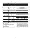
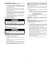
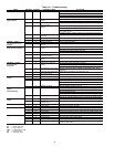
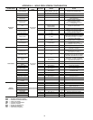
COMPLETE C AND DELUXE D BOARD
SYSTEM TEST
System testing provides the ability to check the control
operation. The control enters a 20-minute Test mode by
momentarily shorting the test pins. All time delays are reduced
by a factor of 15.
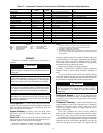
Test Mode — To enter Test mode on Complete C or
Deluxe D controls, cycle the power 3 times within 60 seconds.
The LED (light-emitting diode) will flash a code representing
the last fault when entering the Test mode. The alarm relay will
also power on and off during Test mode. See Tables 15-17. To
exit Test mode, short the terminals for 3 seconds or cycle the
power 3 times within 60 seconds.
NOTE: The Deluxe D control has a flashing code and alarm
relay cycling code that will both have the same numerical
°
°
°
°