


9
Table 2 — Color Code Recommendations
Install Sensors (See Fig. 3-10) —
The PremierLink™
controller can be used with either the T58 Communicating sen-
sor or any combination of CO
2
and space temperature sensors.
Refer to the instructions supplied with each sensor for electrical
requirements.
NOTE: All sensors are field-installed accessories.
SPACE TEMPERATURE (SPT) SENSOR INSTALLA-
TION — There are three types of SPT sensors available from
Carrier: The 33ZCT55SPT space temperature sensor with
timed override button, the 33ZCT56SPT space temperature
sensor with timed override button and set point adjustment, and
the 33ZCT58SPT T58 communicating room sensor with
timed override button, set point adjustment, and manual fan
control.
The space temperature sensors are used to measure the
building interior temperature. The T58 communicating room
sensors measure and maintain room temperature by communi-
cating with the controller. Sensors should be located on an
interior building wall. The sensor wall plate accommodates the
NEMA (National Electrical Manufacturers Association)
standard 2 x 4 junction box. The sensor can be mounted direct-
ly on the wall surface if acceptable by local codes.
Do not mount the sensor in drafty locations such as near air
conditioning or heating ducts, over heat sources such as base-
board heaters, radiators, or directly above wall-mounted light-
ing dimmers. Do not mount the sensor near a window which
may be opened, near a wall corner, or a door. Sensors mounted
in these areas will have inaccurate and erratic sensor readings.
The sensor should be mounted approximately 5 ft from the
floor, in an area representing the average temperature in the
space. Allow at least 4 ft between the sensor and any corner
and mount the sensor at least 2 ft from an open doorway. The
SPT sensor wires are to be connected to terminals in the unit
main control board.
Install the sensor as follows:
1. Locate the two Allen type screws at the bottom of the
sensor.
2. Turn the two screws clockwise to release the cover from
the sensor wall mounting plate.
3. Lift the cover from the bottom and then release it from
the top fasteners.
4. Feed the wires from the electrical box through the open-
ing in the center of the sensor mounting plate.
5. Using two no. 6-32 x 1 mounting screws (provided with
the sensor), secure the sensor to the electrical box.
NOTE: Sensor may also be mounted directly on the
wall using 2 plastic anchors and 2 sheet metal screws
(field-supplied).
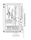
6. Use 20 gage wire to connect the sensor to the controller.
The wire is suitable for distances of up to 500 ft. Use a
three-conductor shielded cable for the sensor and set
point adjustment connections. The standard CCN
communication cable may be used. If the set point adjust-
ment (slidebar) is not required, then an unshielded, 18 or
20 gage, two-conductor, twisted pair cable may be used.
The CCN network service jack requires a separate,
shielded CCN communication cable. Always use sepa-
rate cables for CCN communication and sensor wir-
ing. (Refer to Fig. 5 for wire terminations.)
7. Replace the cover by inserting the cover at the top of the
mounting plate first, then swing the cover down over the
lower portion. Rotate the two Allen head screws counter-
clockwise until the cover is secured to the mounting plate
and locked in position.
NOTE: See Table 3 for thermistor resistance vs temperature
values.
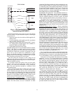
Wiring the Space Temperature Sensor
— To wire the sensor,
perform the following (see Fig. 3-5):
1. Identify which cable is for the sensor wiring.
2. Strip back the jacket from the cables for at least 3 inches.
Strip
1
/
4
-in. of insulation from each conductor. Cut the
shield and drain wire from the sensor end of the cable.
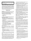
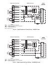
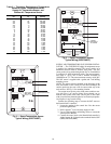
3. Connect the sensor cable as follows:
a. Connect one wire from the cable to (BLU) wire on
J6-7 analog connector on the controller. Connect
the other end of the wire to the left terminal on the
SEN terminal block of the sensor.
b. Connect another wire from the cable to (BRN)
J6-6 analog connector on the controller. Connect
the other end of the wire to the remaining open ter-
minal on the SEN terminal block.
c. On 33ZCT56SPT thermostats, connect the remain-
ing wire to the (BLK) STO on J6-5 connector on
the controller. Connect the other end of the wire to
the SET terminal on the sensor.
d. In the control box, install a no. 10 ring type crimp
lug on the shield drain wire. Install this lug under
the mounting screw of the PremierLink controller.
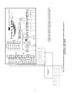
e. On 33ZCT56SPT thermostats install a jumper
between the two center terminals (right SEN and
left SET). See Fig. 4.
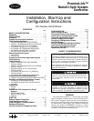
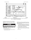
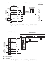
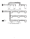
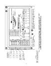
f. Refer to Fig. 5 for 33ZCT58SPT thermostat wir-
ing. Once the T58 sensor is powered up, all of the
graphic icons on the LCD (liquid crystal display)
display will be energized for a few seconds. The
graphical icons will then turn off and the T58 sen-
sor will energize the three-digit numeric display.
The value “58” will be displayed for two seconds.
After 2 seconds, the LCD will display the default
space temperature value.
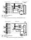
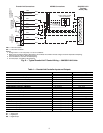
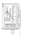
NOTE: See Fig. 6 for space temperature sensor averaging.
SIGNAL TYPE
CCN BUS WIRE
COLOR
CCN PLUG PIN
NUMBER
+
Red 1
Ground
White 2
–
Black 3