


28
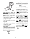
To access the sub-mode to change the Unoccupied OAT
Lockout Setpoint, press the down arrow to scroll down until
the Navigator™ module display reads:
SETP
OATL
>NTLO
UHDB
To view an expansion of the sub-mode, press the
and keys simultaneously and the Navigator will
display:
>NTLO
UNOCC. OAT LOCKOUT
TEMP
The Navigator will remain in the expanded display mode
until the key is pressed. Use the arrow keys to view
expansions for any of the other sub-modes within the Setpoint
mode.
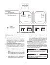
Password Protection —
If an area is entered that is
password protected or an item is selected for change that is
password protected, the Navigator will display:
Enter Password
1111 (default password)
The first digit of the password will be flashing. Hold either
of the arrow keys down to change the value of the first digit (if
necessary) and press to accept. Repeat the process for
the remaining three digits.
The message “Invalid Password” is displayed if the pass-
word is not correct. The password can not be disabled from the
Navigator, nor can it be changed.
Forcing Values and Configuring Items —
Cer-
tain items are allowed to be forced and other items are user-
configurable. Both of these changes can be made using the
Navigator.
CONFIGURATION
The following sections describe the computer configuration
screens which are used to configure the PremierLink™ con-
troller. The screens shown may be displayed differently when
using different Carrier software.
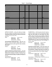
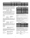
Points Display Screen —
The Points Display screen is
used to monitor and change the PremierLink controller set
points. See Table 7.
SPACE TEMPERATURE — This point displays the space
temperature from the 10K thermistor (Type III) located in the
space.
Space
Temperature: Display Units: Degrees F (Degrees C)
Default Value: –40.0
Display Range: –40.0 to 245.0
Network Access: Read/Write
SUPPLY AIR TEMPERATURE — The Supply Air Temper-
ature point displays the temperature of the air leaving the unit,
downstream of any cool or heat sources. Temperature is mea-
sured by a 10K thermistor (Type III). This sensor is required
for proper function of the heating, cooling, and the economizer.
Supply Air
Temperature: Display Units: Degrees F (Degrees C)
Default Value: 0.0
Display Range: –40.0 to 245.0
Network Access: Read/Write
OUTDOOR AIR TEMPERATURE — Temperature of the
air leaving the unit downstream of any cool or heat sources,
measured by a 10K thermistor (Type III). This sensor is
required for proper function of the heating, cooling, and the
economizer.
Outdoor Air
Temperature: Display Units: Degrees F (Degrees C)
Default Value: 0.0
Display Range: –40.0 to 245.0
Network Access: Read/Write
CONTROL SET POINT — This point displays the current
controlling set point when a heat or cool mode is active. If there
is not an active heat or cool set point, the set point of the last
mode is displayed. Upon reset or start-up, the proper cooling
set point is displayed, depending on occupancy. In the thermo-
stat mode, this point is not used for equipment control.
Control Set Point: Display Units: Degrees F (Degrees C)
Default Value: Unoccupied Cool
Setpoint
Display Range: 35 to 110
Network Access: Read Only
COOLING PERCENT TOTAL CAPACITY — The Cooling
Percent Total Capacity point is used to display the current
Cooling Capacity. When cooling is enabled, the percent of
cooling being delivered is determined by the following formula
for the number of compressor stages confirmed:
% Output Capacity = (# of active stages/Total stages) * 100.
Cooling Percent
Total Capacity: Display Units: % output capacity
Default Value: 0
Display Range: 0 to 100
Network Access: Read Only
HEATING PERCENT TOTAL CAPACITY — The Heating
Percent Total Capacity point is used to display the current
Heating Capacity.
When heat is enabled, the percent of heat being delivered is
determined by the following formula for electric heat:
% Output Capacity = (# of active stages/Total stages) * 100
Heating Percent
Total Capacity: Display Units: % output capacity
Default Value: 0
Display Range: 0 to 100
Network Access: Read Only
ECONOMIZER ACTIVE — The Economizer Active point
displays the status of the economizer for free cooling. When
the outdoor conditions match the desired indoor conditions, the
economizer will be enabled for outdoor air assisted cooling.
Economizer
Active: Display Units: Discrete ASCII
Default Value: No
Display Range: No/Yes
Network Access: Read Only
SUPPLY FAN RELAY — This point displays the command-
ed state of the Supply Fan Relay.
Supply Fan
Relay: Display Units: Discrete ASCII
Default Value: Off
Display Range: Off/On
Network Access: Read/Write
ENTER
ESCAPE
ESCAPE
ENTER