


20
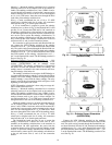
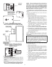
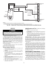
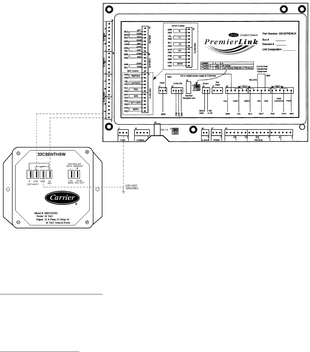
Connect the 4-20 mA In terminal on the enthalpy switch/
receiver to the 4-20 mA Out terminal on the return air enthalpy
sensor. Connect the 24-36 VDC Out terminal on the enthalpy
switch/receiver to the 24-36 VDC In terminal on the return air
enthalpy sensor. See Fig. 21.
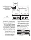
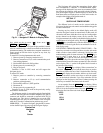
Enthalpy Switch/Reciever Jumper Settings
— There are two
jumpers. One jumper determines the mode of the enthalpy
switch/receiver. The other jumper is not used. To access the
jumpers, remove the 4 screws holding the cover on the
enthalpy switch/receiver and then remove the cover. The fac-
tory settings for the jumpers are M1 and OFF.
The mode jumper should be set to M2 for differential en-
thalpy control. The factory test jumper should remain on OFF
or the enthalpy switch/receiver will not calculate enthalpy.
Enthalpy Sensor Jumper Settings
— There are two jumpers.
One jumper determines the mode of the enthalpy sensor. The
other jumper is not used. To access the jumpers, remove the 4
screws holding the cover on the enthalpy sensor and then
remove the cover. The factory settings for the jumpers are M3
and OFF.
The mode jumper should be set to M3 for 4 to 20 mA
output. The factory test jumper should remain on OFF or the
enthalpy sensor will not calculate enthalpy.
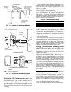
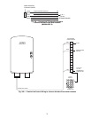
OUTDOOR AND RETURN AIR ENTHALPY SEN-
SORS — The differential enthalpy control is supplied as a
field-installed accessory to be used with the Economizer damp-
er control option. The differential enthalpy control provides
two enthalpy sensors for sensing the outdoor air and return air
conditions, and a differential enthalpy controller.
NOTE: The differential enthalpy control must be set to the “D”
setting for differential enthalpy control to work properly.
The differential enthalpy control senses the outdoor and
return air sensors and provides a dry contact switch input to the
PremierLink Controller. Locate the controller in place of an
existing economizer controller or near the actuator. The mount-
ing plate may not be needed if existing bracket is used.
A closed contact indicates that outside air is preferred to the
return air. An open contact indicates that the economizer
should remain at minimum position.
The solid-state return air enthalpy sensor senses and com-
bines the temperature and humidity levels of outdoor and re-
turn air. The sensors provide information for comparison of
outdoor temperature and humidity to return air temperature and
humidity in order to determine the most economical mixture of
air.
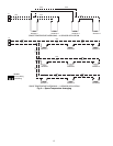
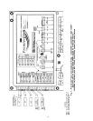
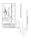
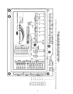
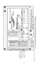
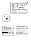
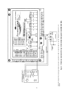
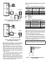
Fig. 20 — Typical Wiring Schematic — Carrier Rooftop Unit with PremierLink™ Controls
*Used with Differential Enthalpy Control only.