


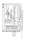
24
Economizer with Johnson 4 to 20 mA Actua-
tor —
The PremierLink Controller can be connected to an
economizer that uses a Johnson 4 to 20 mA actuator.
DRIVE DIRECTION — The actuator drive direction is
dependent upon the position of Switch 3 and the spring return
direction. See Table 5. The actuator is factory set for Direct
Acting (DA) operation with Switch 3 in the DA position. An
increasing control signal drives the actuator away from the
spring return position in DA mode. The actuator should be
installed in the DA mode so damper will close automatically
on power shut down.
If Reverse Acting (RA) operation is desired, move Switch 3
to the RA position. An increasing control signal drives the
actuator toward the spring return position in RA mode.
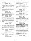
SWITCH SELECTION — The type of input control signal is
determined by the position of Switch 5. With Switch 5 in the
VDC position (factory setting), the signal is DC voltage. With
Switch 5 min the mA position, the input signal changes to
current input. See Fig. 28 and Table 6. The switch should be set
to mA for use with PremierLink controller.
NOTE: To change the factory setting, use a
1
/
8
-in. (3-mm)
flat-blade screwdriver to position the mode switch to the alter-
nate setting.
Table 5 — Actuator Drive Direction Settings
LEGEND
Table 6 — Mode Selection Information
NOTE: The 6 to 9 VDC setting of Switch 1 overrides switch 4.
WIRING (See Fig. 29-30B) — The wires for power and
signal transmission from PremierLink to economizer are field-
supplied. To connect the Economizer Johnson Actuator to
PremierLink controller, connect the pink wire on actuator to
purple wire on PremierLink J9-1. See Fig. 30A.
For the Belimo Actuator, connect the white wire on the ac-
tuator to J9-1 on the PremierLink controller. See Fig. 30B.
NOTE: To retrofit PremierLink Controller to older 4 to 20 mA
actuator, connect the red wire on the actuator wire harness to
the purple wire on the PremierLink J9-1. Connect the yellow
and white wires from the actuator wire harness to the 24-volt
AC transformer on equipment. See Fig. 29.
POSITION OF
SWITCH 3 AND THE
DIRECTION OF
SPRING RETURN
DRIVE
DRIVE DIRECTION
WITH A MINIMUM
INPUT SIGNAL
DRIVE DIRECTION
WITH A MAXIMUM
INPUT SIGNAL
DA/CCW
CCW CW
RA/CCW
CW CCW
DA/CW
CW CCW
RA/CW
CCW CW
CCW —
Counterclockwise
CW —
Clockwise
DA —
Direct Action
RA —
Reverse Action
MODE
SWITCHES
SWITCH FUNCTIONS
FACTORY
SETTINGS
5
VDC or mA VDC
4
0 to 10 VDC (0 to 20 mA or
2 to 10 VDC (4 to 20 mA)
0 to 10
3
Direct Acting (DA) or
Reverse Acting (RA)
DA
2
FIXED or AUTO FIXED
1
— or 6 to 9 VDC —
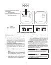
IMPORTANT: Make sure the common side is grounded
for both the PremierLink power and the actuator power.
This is especially important if separate transformers are
used.
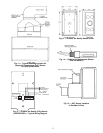
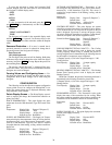
24 VAC
SENSOR
MIN.
POS
TR
P1
P
T1
T
TR1
24 VAC
TRANSFORMER
Q769B
ADAPTER
21
-+
+
-
+
+
-
-
LOOP
ISOLATOR
PREMIERLINK
CONTROL
J9
M7415
ACTUATOR
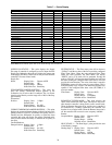
24 VAC
SENSOR
MIN.
POS
TR
P1
P
T1
T
TR1
24 VAC
TRANSFORMER
(SEPARATE,
FIELD-SUPPLIED)
500 OHM
RESISTOR
21
-+
+
-
PREMIERLINK
CONTROL
J9
M7415
ACTUATOR
Q769C
ADAPTER
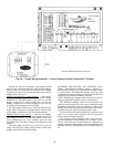
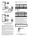
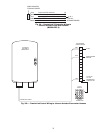
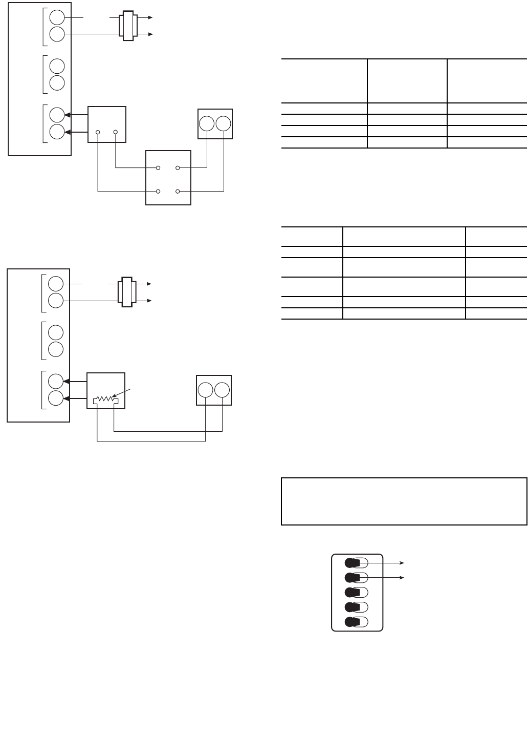
Fig. 26 — PremierLink™ Control Wiring to
Q769B Adapter and Actuator
Fig. 27 — PremierLink Control Wiring to
Q769C Adapter and Actuator
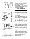
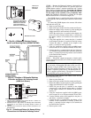
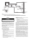
5 4 3 2 1
VDC
0-10
DA
FIXED
—
mA
2-10
RA
AUTO
6-9
MOVE TO LEFT
FOR 4-20mA CONTROL
WITH PREMIERLINK
CONTROLLER
Fig. 28 — Position of Actuator Mode Switches
(Factory Default)