


18
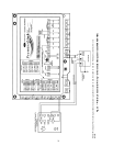
Connect to CCN Communication Bus —
The
PremierLink™ controller connects to the bus in a daisy chain
arrangement. Negative pins on each component must be
connected to respective negative pins and likewise positive pins
on each component must be connected to respective positive
pins. The controller signal pins must be wired to the signal
ground pins. Wiring connections for CCN must be made at the
3-pin plug.
At any baud (9600, 19200, 38400 baud), the number of con-
trollers is limited to 239 devices maximum. Bus length may not
exceed 4000 ft, with no more than 60 total devices on any
1000-ft section. Optically isolated RS-485 repeaters are
required every 1000 ft.
NOTE: Carrier device default is 9600 baud.
COMMUNICATION BUS WIRE SPECIFICATIONS —
The CCN Communication Bus wiring is field-supplied and
field-installed. It consists of shielded three-conductor cable
with drain (ground) wire. The cable selected must be identical
to the CCN Communication Bus wire used for the entire net-
work. See Table 4 for recommended cable.
Table 4 — Recommended Cables
NOTE: Conductors and drain wire must be at least 20 AWG
(American Wire Gage), stranded, and tinned copper. Individual
conductors must be insulated with PVC, PVC/nylon, vinyl,
Teflon, or polyethylene. An aluminum/polyester 100% foil
shield and an outer jacket of PVC, PVC/nylon, chrome vinyl,
or Teflon with a minimum operating temperature range of
–20 C to 60 C is required.
The communication bus shields must be tied together at
each system element. If the communication bus is entirely
within one building, the resulting continuous shield must be
connected to ground at only one single point. If the communi-
cation bus cable exits from one building and enters another
building, the shields must be connected to the grounds at a
lightning suppressor in each building (one point only).
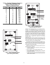
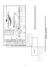
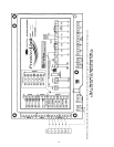
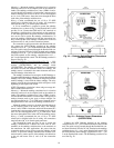
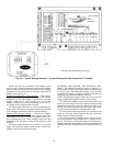
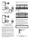
Enthalpy and Differential Enthalpy Control
(Fig. 18-23) —
There are two options for field-supplied
enthalpy and differential enthalpy control: the enthalpy switch/
receiver option, and the outdoor and return air sensor option.
Either option can be used to indicate when the outdoor air is
suitable for free cooling.
ENTHALPY SWITCH/RECEIVER — The accessory en-
thalpy switch/receiver (33CSENTHSW) senses temperature
and humidity of the air surrounding the device and calculates
the enthalpy when used without an enthalpy sensor. The relay
is energized when enthalpy is high and deenergized when
enthalpy is low (based on ASHRAE 90.1 criteria). If an acces-
sory enthalpy sensor (33CSENTSEN) is attached to the return
air sensor input, then differential enthalpy is calculated. The
relay is energized when the enthalpy detected by the return air
enthalpy sensor is less than the enthalpy at the enthalpy switch/
receiver. The relay is deenergized when the enthalpy detected
by the return air enthalpy sensor is greater than the enthalpy at
the enthalpy switch/receiver (differential enthalpy control). See
Fig. 18 and 19.
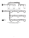
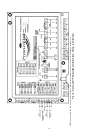
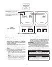
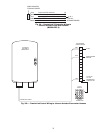
Outdoor Enthalpy Control Installation (Fig. 20)
— Outdoor
enthalpy control requires only an enthalpy switch/receiver
(33CSENTHSW). The enthalpy switch/receiver is mounted in
the outdoor air inlet and calculates outdoor air enthalpy. The
enthalpy switch/receiver energizes the relay output when the
outdoor enthalpy is above 28 BTU/lb OR dry bulb temperature
is above 75 F and is deenergized when the outdoor enthalpy is
below 27 BTU/lb AND dry bulb temperature is below 74.5 F.
The relay output is wired to the unit economizer which will
open or close depending on the output of the switch.
NOTE: The enthalpy calculation is done using an average alti-
tude of 1000 ft above sea level.
MANUFACTURER CABLE PART NO.
Alpha
2413 or 5463
American
A22503
Belden
8772
Columbia
02525
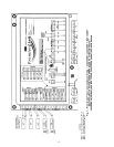
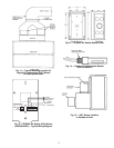
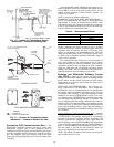
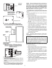
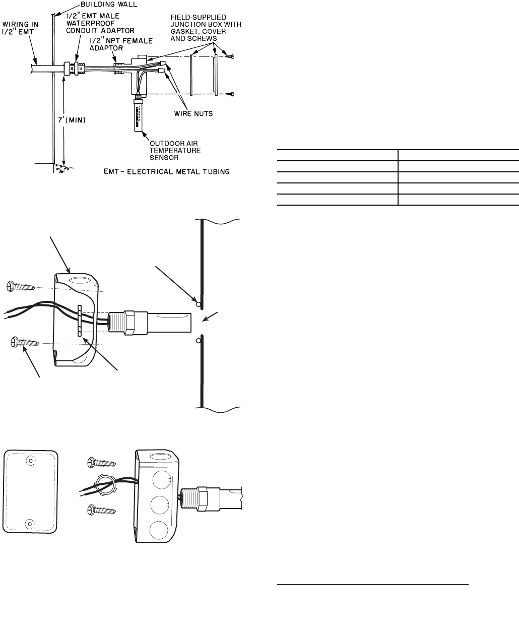
Fig. 16 — Outdoor Air Temperature Sensor
Installation — Located in Building Wall
DUCT MOUNTED (EXPLODED VIEW)
1/4" BEAD
SILICONE
SEALER
1.125"
DIA.
HOLE
OA
DUCT
OAT SENSOR
1/2" CONDUIT NUT
2 #10 DRILL/TAP
SCREWS
(FIELD SUPPLIED)
2 x 4 x 1.5 IN. ELECTRICAL BOX
(FIELD SUPPLIED)
OUTSIDE AIR DUCT
LEGEND
Fig. 17 — Outdoor Air Temperature Sensor
Installation — Located in Outdoor Air Duct
OA —
Outdoor Air
OAT —
Outdoor Air Temperature