


29
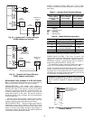
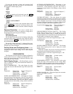
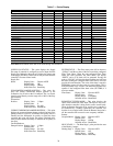
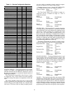
Table 7 — Points Display
NOTE:
Bold
values indicate points that can be forced through communications.
SUPPLY FAN STATUS — This point displays the Supply
Fan status if controller is configured to receive input from the
Supply Fan. Otherwise this point will display the output state
of the Supply Fan Relay. This mode can only be used when the
controller is in sensor control mode.
Supply Fan
Status: Display Units: Discrete ASCII
Default Value: Off
Display Range: Off/On
Network Access: Read Only
ECONOMIZER DAMPER POSITION — This point dis-
plays the current commanded damper position of the
economizer 4 to 20 mA on the J-9 connector. The 4 to 20 mA
signal is scaled linearly over the range of 0 to 100% of the Sup-
ply Fan Relay.
Economizer
Position: Display Units: % Open
Default Value: 0
Display Range: 0 to 100
Network Access: Read/Write
CURRENT MINIMUM DAMPER POSITION — This point
displays the current minimum damper position if an Indoor Air
Quality routine is not active. If an Indoor Air Quality sensor is
installed and the differential air quality set point has been
exceeded, this point will display the current calculated mini-
mum position deemed necessary to maintain the air quality in
the space.
Current Minimum
Damper Position: Display Units: % Open
Default Value: 0
Display Range: 0 to 100
Network Access: Read Only
FILTER STATUS — The filter status point will be shown as
“CLEAN” until the run time of the fan exceeds the configured
Filter Timer Hours. When the user-configured Filter Timer
Hours has been exceeded, the Filter Status will display
“DIRTY” and a CCN alarm will be generated. Forcing the
point to “CLEAN” will clear the alarm condition and will reset
the timer. (Setting the configured filter timer value to zero will
provide the same function.) The value of the timer is stored in
EEPROM to protect it in the event of a power failure. This is
done periodically every 24 hours. The filter timer function only
operates if the configured filter timer value (FLTTMR) is a
non-zero number.
Filter Status: Display Units: Discrete ASCII
Default Value: Clean
Display Range: Clean/Dirty
Network Access: Read/Write
REMOTE OCCUPIED MODE — This point displays the
status of the remote time clock input. This input is only avail-
able when the controller is being used in sensor control mode.
When the Remote Start point is on, and the zone controller is
not controlled by a Linkage Thermostat, the controller will
function in an occupied mode. When the Remote Start point is
off, the controller will revert to its own occupancy schedule.
Remote
Occupied Mode: Display Units: Discrete ASCII
Default Value: Off
Display Range: Off/On
Network Access: Read/Write
HEAT STAGE 1 — The Heat Stage 1 point provides the state
of the Heating 1 output.
Heating Stage 1: Display Units: Discrete ASCII
Default Value: Off
Display Range: Off/On
Network Access: Read Only
DESCRIPTION VALUE UNITS STATUS FORCE NAME
Space Temperature
72.2
dF SPT
Supply Air Temperature
67.1
dF SAT
Outdoor Air Temperature
48.8
dF OAT
Control Setpoint 0.0 dF CLSP
Cooling % Total Capacity 0 % CCAP
Heating % Total Capacity 0 % HCAP
Economizer Active Yes ECOS
Supply Fan Relay
On
SF
Supply Fan Status On SFS
Economizer Position
26.2
%ECONPOS
Current Min Damper Pos 20 % IQMP
Filter Status
Clean
FLTS
Remote Occupied Mode
Off
RMTOCC
Heat Stage 1 Off HS1
Heat Stage 2 Off HS2
Heat 3/Exhaust/Rev Valve Off H3_EX_RV
Enthalpy
Low
ENTH
Indoor Air Quality
367.9
IAQI
Indoor Air Quality Setpt 1050.0 IAQS
Outdoor Air Quality
0.0
Sensor failure OAQ
Fire Shutdown
Normal
FSD
SPT Offset
0.0
^F STO
Compressor 1 Off CMP1
Compressor 2 Off CMP2
Compressor Safety Off CMPSAFE