


11
Perform the following steps if state or local code requires
the use of conduit, or if your installation requires a cable length
of more than 8 ft:
1. Secure the probe to the duct with two field-supplied self-
drilling screws.
2. If you are extending cable length beyond 8 ft, use plenum
rated, 20 AWG, twisted pair wire.
3. Connect the sensor leads to the PremierLink™ control-
ler’s wiring harness terminal board at the terminals la-
beled SAT (ORN) and GND (BRN).
4. Neatly bundle and secure excess wire.
INDOOR AIR QUALITY CO
2
SENSOR INSTALLATION
(IAQ) — The indoor air quality sensor accessory monitors
carbon dioxide (CO
2
) levels. This information is used to moni-
tor IAQ levels. Three types of sensors are provided. The wall
sensor can be used to monitor the conditioned air space.
Sensors use infrared technology to measure the levels of CO
2
present in the air. The wall sensor is available with or without
an LCD readout to display the CO
2
level in ppm.
The CO
2
sensors are all factory set for a range of 0 to
2000 ppm and a linear mA output of 4 to 20. Refer to the
instructions supplied with the CO
2
sensor for electrical require-
ments and terminal locations.
To accurately monitor the quality of the air in the condi-
tioned air space, locate the sensor near a return air grille (if
present) so it senses the concentration of CO
2
leaving the
space. The sensor should be mounted in a location to avoid
direct breath contact.
Do not mount the IAQ sensor in drafty areas such as near
supply ducts, open windows, fans, or over heat sources. Allow
at least 3 ft between the sensor and any corner. Avoid mounting
the sensor where it is influenced by the supply air; the sensor
gives inaccurate readings if the supply air is blown directly onto
the sensor or if the supply air does not have a chance to mix
with the room air before it is drawn into the return airstream.
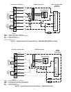
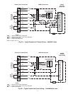
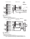
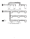
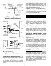
Wiring the Indoor Air Quality Sensor
— To wire the sensors
after they are mounted in the conditioned air space or outdoor
location, see Fig. 7 and 8 and the instructions shipped with the
sensors. For each sensor, use two 2-conductor 18 AWG
(American Wire Gage) twisted-pair cables (unshielded) to con-
nect the separate isolated 24 vac power source to the sensor and
to connect the sensor to the control board terminals. To connect
the sensor to the control, identify the positive (4 to 20 mA) and
ground (SIG COM) terminals on the sensor. Connect the
4-20 mA terminal to terminal IAQ (RED) and connect the
SIG COM terminal to terminal GND (BRN).
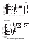
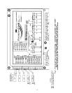
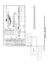
OUTDOOR AIR QUALITY CO
2
SENSOR INSTALLA-
TION (OAQ) — The Outdoor Air CO
2
sensor is designed to
monitor carbon dioxide (CO
2
) levels in the air and interface
with the ventilation damper in an HVAC system. The OAQ
sensor is packaged with an outdoor cover. See Fig. 12 and 13.
The outdoor air CO
2
sensor must be placed in an area that is
representative of the entire conditioned space. A mounting
height of 6 feet is recommended. For installation where it is not
necessary to reach the control, it may be mounted higher on the
wall or on the ceiling, provided the location represents a good
sampling of air.
Wiring the Outdoor Air CO
2
Sensor — Power requirements
are 18 to 36 vac RMS 50/60 Hz; 18 to 42 vdc polarity protected/
dependent; and 70 mA average, 100 mA peak at 24 vdc. All
system wiring must be in compliance with all applicable local
and national codes. A dedicated power supply is required for
this sensor. A two-wire cable is required to wire the dedicated
power supply for the sensor. The two wires should be connected
to the power supply and terminals 1 and 2. To connect the sen-
sor to the control, identify the positive (4 to 20 mA) and ground
(SIG COM) terminals on the sensor. Connect the 4 to 20 mA
terminal OAQ (BLU) terminal J5-2. Connect the SIG COM ter-
minal to terminal GND (BRN) terminal J5-3. See Fig. 12.
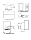
OUTDOOR AIR TEMPERATURE SENSOR (Fig. 14-17) —
The OAT sensor must be located properly. The sensor must be
installed immediately upstream from outdoor air damper
where it will accurately sense the temperature of the outdoor
air entering the mixing box. See Fig. 14 and 15. For applica-
tions without economizer, the sensor may be located in the out-
door air duct near the outdoor air intake (Fig. 15) or on the
exterior of the building. The thermistor has a range of –40 to
245 F and a resistance of 10,000 ohms at 77 F.
Do not mount the sensor in direct sunlight. Inaccurate read-
ings may result. Do not mount the sensor near the exhaust from
air-handling units or compressors, near leakage drafts of indoor
air, or near shrubbery or trees, or under direct water runoff.
If the sensor is to be mounted in the outdoor air duct, a field-
supplied 2 x 4-in. by 1
1
/
2
-in. deep electrical box is required.
Remove the cover and enter the knockout from the rear of the
box. Install the sensor through the opening so that the sensor
leads are inside the electrical box. Secure the sensor to the elec-
trical box using a field-supplied
1
/
2
-in. conduit nut. Drill a
1
3
/
16
-in. hole in the outdoor air duct about a foot upstream of
the outdoor air damper. Apply a
1
/
4
-in. bead of silicone type
sealer around the opening and install the sensor through the
hole. Secure the electrical box to the duct using 2 field-
supplied, No. 10 sheet metal screws. See Fig. 17.
If the sensor is installed outdoors, a field-supplied
1
/
2
-in. LB
type conduit body, gasket, cover, and
1
/
2
-in. EMT compression
connector are required. Install the OAT sensor into the opening
at the end of the LB conduit body. Install the
1
/
2
-in. EMT
connector into the rear opening. Tighten each securely to
prevent water leakage into the assembly. Mount the assembly
onto the
1
/
2
-in. EMT conduit and secure by tightening the
compression connector nut. After the sensor wiring is complet-
ed, secure the gasket and cover in place using the screws
provided with the cover. See Fig. 16.
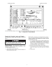
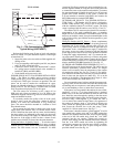
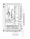
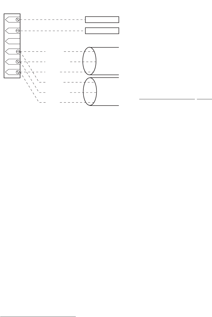
VAC
24 VAC
BLACK (-)
WHITE (GND)
RED (+)
BLACK (-)
WHITE (GND)
RED (+)
CCN
COM
J2
(COM)
COM
CCN-
GND
CCN+
T58 SENSOR
J6-6 SDT (COM)
J4-3 (24 VAC)
FIELD WIRING
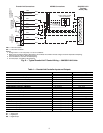
Fig. 5 — T58 Communicating Sensor
Typical Wiring (33ZCT58SPT)