


19
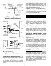
Mounting — Mount the enthalpy switch/receiver in a location
where the outdoor air can be sampled (such as the outdoor air
intake). The enthalpy switch/receiver is not a NEMA 4 enclo-
sure and should be mounted in a location that is not exposed to
outdoor elements such as rain or snow. Use two field-supplied
no. 8 x
3
/
4
-in. TEK screws. Insert the screws through the holes
in the sides of the enthalpy switch/receiver.
Wiring — Carrier recommends the use of 18 to 22 AWG
twisted pair or shielded cable for all wiring. All connections
must be made with
1
/
4
-in. female spade connectors.
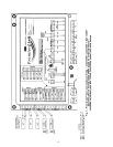
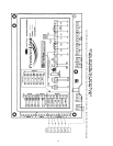
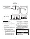
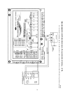
A 24 vac transformer is required to power the enthalpy
switch/receiver; as shown in Fig. 20, the PremierLink™ board
provides 24 vac. Connect the GND and 24 VAC terminals on
the enthalpy switch/receiver to the terminals on the transform-
er. On some applications, the power from the economizer har-
ness can be used to power the enthalpy switch/receiver. To
power the enthalpy switch/receiver from the economizer har-
ness, connect power of the enthaply switch/receiver to the red
and brown wires (1 and 4) on the economizer harness.
For connection to split systems units with PremierLink con-
trol, connect the LOW Enthalpy terminal on the enthalpy
switch/receiver to J4 — pin 2 of the PremierLink control on the
unit. The switch can be powered through the PremierLink con-
trol board if desired. Wire the 24 VAC terminal on the enthalpy
switch/receiver to J4 — pin 1 on the PremierLink control. Wire
the GND terminal on the enthalpy switch/receiver to J1 —
pin 2 on the PremierLink control. The HI Enthalpy terminal is
not used. See Fig. 20.
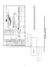
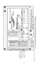
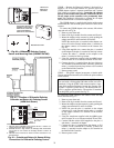
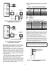
Differential Enthalpy Control Installation (Fig. 21)
— Dif-
ferential enthalpy control requires both an enthalpy switch/
receiver (33CSENTHSW) and an enthalpy sensor
(33CSENTSEN). The enthalpy switch/receiver is mounted in
the outdoor air inlet and calculates outdoor air enthalpy. The
enthalpy sensor is mounted in the return airstream and calcu-
lates the enthalpy of the indoor air.
The enthalpy switch/receiver energizes the HI Enthalpy re-
lay output when the outdoor enthalpy is greater than the indoor
enthalpy. The LOW Enthalpy terminal is energized when the
outdoor enthalpy is lower than the indoor enthalpy. The relay
output is wired to the unit economizer which will open or close
depending on the output of the switch.
NOTE: The enthalpy calculation is done using an average alti-
tude of 1000 ft above sea level.
Mounting — Mount the enthalpy switch/receiver in a location
where the outdoor air can be sampled (such as the outdoor air
intake). The enthalpy switch/receiver is not a NEMA 4 enclo-
sure and should be mounted in a location that is not exposed to
outdoor elements such as rain, snow, or direct sunlight. Use
two field-supplied no. 8 x
3
/
4
-in. TEK screws. Insert the screws
through the holes in the sides of the enthalpy switch/receiver.
Mount the enthalpy sensor in a location where the indoor air
can be sampled (such as the return air duct). The enthalpy
sensor is not a NEMA 4 enclosure and should be mounted in a
location that is not exposed to outdoor elements such as rain or
snow. Use two field-supplied no. 8 x
3
/
4
-in. TEK screws. Insert
the screws through the holes in the sides of the enthalpy sensor.
Wiring — Carrier recommends the use of 18 to 22 AWG
twisted pair or shielded cable for all wiring. All connections
must be made with
1
/
4
-in. female spade connectors.
The PremierLink board provides 24 vac to power the
enthalpy switch/receiver. Connect the GND and 24 VAC
terminals on the enthalpy switch/receiver to the terminals on
the transformer. On some applications, the power from the
economizer harness can be used to power the enthalpy switch/
receiver. To power the enthalpy switch/receiver from the econ-
omizer harness, connect power of the enthaply switch/receiver
to the red and brown wires (1 and 4) on the economizer
harness.
Connect the LOW Enthalpy terminal on the enthalpy
switch/receiver to J4 — pin 2 of the PremierLink control on the
unit. The switch can be powered through the PremierLink con-
trol board if desired. Wire the 24 VAC terminal on the enthalpy
switch/receiver to J4 — pin 1 on the PremierLink control. Wire
the GND terminal on the enthalpy switch/receiver to J1 — pin
2 on the PremierLink control. The HI Enthalpy terminal is not
used. See Fig. 20.
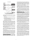
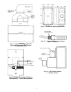
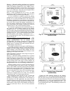
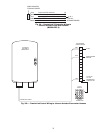
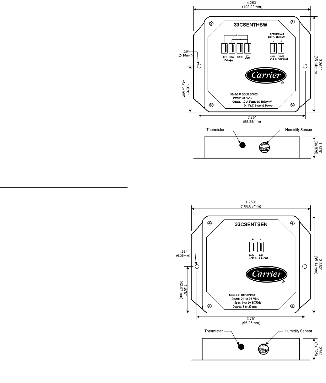
Fig. 18 — Enthalpy Switch/Receiver Dimensions
(33CSENTHSW)
Fig. 19 — Enthalpy Sensor Dimensions
(33CSENTSEN)