


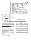
21
Wiring Enthalpy Sensors
— To wire the enthalpy sensor, per-
form the following (see Fig. 24 and 25):
NOTE: To mount outdoor air sensor remotely, remove it from
back of enthalpy control and follow steps 3 and 6.
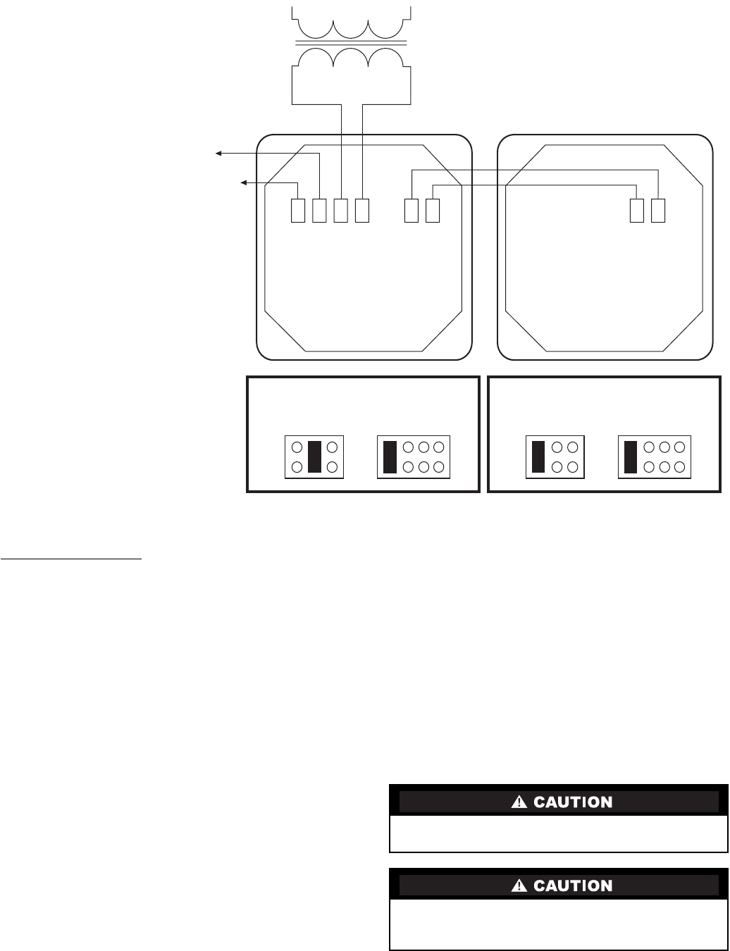
1. Use a 2-conductor, 18 or 20 AWG, twisted pair cable to
connect the return air enthalpy sensor to the differential
enthalpy control. Use a 4-conductor, 18 or 20 AWG cable
to connect the enthalpy control to the PremierLink con-
troller and power transformer.
2. At the differential enthalpy control remove the factory-
installed resistor from the SR and (+) terminals.
3. Connect the RED wire from the 2-conductor cable which
originates from the return air enthalpy sensor to the
SR (+) terminal. Connect the BLK wire to the SR (–)
terminal.
4. Connect the following 4 wires from the 4-wire conduc-
tive cable to the differential enthalpy controller:
a. Connect the RED wire to the 24 vac terminal
(TR1) on enthalpy control and to pin 1 on 12-pin
harness.
b. Connect the BRN wire to the 24 vac GND terminal
(TR) on enthalpy sensor and to pin 4 on 12-pin
harness.
c. Connect the ORN wire to J4-2 on PremierLink
controller and to terminal 3 on enthalpy sensor.
d. Connect the RED wire to J4-1 on PremierLink
controller and to terminal 2 on enthalpy sensor.
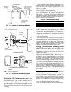
5. At the return air enthalpy sensor, strip 3 in. of jacket from
the cable and remove
1
/
2
in. of insulation from each
conductor.
6. Connect the RED wire to (+) spade connector on the
sensor. Connect the BLK wire to (S) spade connector on
the sensor. Use wire nuts or closed-end crimp-type con-
nectors to fasten the connections securely. See Fig. 22.
Economizer —
The PremierLink™ controller will inter-
face with the 40RM economizer. Economizers will contain a
Honeywell actuator (Honeywell part number M7415).
An adapter (Honeywell part number Q769B or Q769C is
preferred) must be used to enable the 4 to 20 mA signal from
the PremierLink controller to control the position of the econo-
mizer. Refer to Honeywell Q769B and Q769C accessory in-
stallation instructions for wiring details.
Disconnect power supply before making wiring connec-
tions to prevent electrical shock and equipment damage.
To avoid permanent damage to the PremierLink 4 to
20 mA connection, a signal loop isolator must be installed
when using the Q769B adapter.
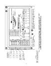
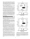
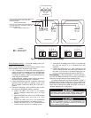
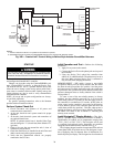
24 VAC OUTPUT FROM N/C CONTACT WHEN THE
OUTDOOR ENTHALPY IS LESS THAN THE
INDOOR ENTHALPY
(ENABLE ECONOMIZER)
24 VAC OUTPUT FROM N/O CONTACT WHEN THE
OUTDOOR ENTHALPY IS GREATER THAN THE
OUTDOOR ENTHALPY
(ENABLE ENERGY RECYCLER)
24 VAC
SECONDARY
HI
LOW
GND 24
VAC
ENTHALPY
4-20
mA
IN
24-36
VDC
OUT
120 VAC LINE VOLTAGE
JUMPER SETTINGS FOR 33CSENTHSW
M1
M2
M3
0%
50%
100%
OFF
33CSENTHSW
JUMPER SETTINGS FOR 33CSENTSEN
M1
M2
M3
0%
50%
100%
OFF
33CSENTSEN
4-20
mA
OUT
24-36
VDC
IN
Fig. 21 — Differential Enthalpy Control Wiring
LEGEND
N/C —
Normally Closed
N/O —
Normally Open