


30
HEAT STAGE 2 — The Heat Stage 2 point provides the state
of the Heating 2 output.
Heating Stage 2: Display Units: Discrete ASCII
Default Value: Off
Display Range: Off/On
Network Access: Read Only
HEAT STAGE 3, EXHAUST FAN, OR REVERSING
VALVE — This point displays the commanded state of auxil-
iary output. This output can be configured to control a third
stage of heat, an exhaust fan or a reversing valve on some heat
pump units.
In the exhaust fan mode with continuous exhaust con-
figured, this point may control a bank of lights or another
indicator that should remain ON whenever the controller is in
the occupied mode.
Heat 3, Exhaust,
Rev Valve: Display Units: Discrete ASCII
Default Value: Off
Display Range: Off/On
Network Access: Read Only
ENTHALPY — This point displays the current status of an
outdoor air or differential enthalpy input. This point may be
broadcast to other controllers or received from a controller
which supports global broadcast of the ENTH variable.
Enthalpy: Display Units: Discrete ASCII
Default Value: High
Display Range: High/Low
Network Access: Read/Write
INDOOR AIR QUALITY (IAQ) — The Air Quality point
displays the indoor air quality reading from a CO
2
sensor
installed in the space. The CO
2
sensor maintains differential
indoor air quality for demand control ventilation per ASHRAE
Standard 62-1999. The controller can be configured to generate
an alarm when the control is in occupied mode and the CO
2
level exceeds the high or low limit set.
Indoor Air
Quality (ppm): Display Units: None shown (parts per
million implied)
Default Value: 0
Display Range: 0 to 5000
Network Access: Read/Write
INDOOR AIR QUALITY SET POINT — This point dis-
plays the current Indoor Air Quality set point. The set point is
determined by the configured Indoor Air Quality differential
and the current outdoor air quality value. If an outdoor air
quality value is not received, the controller will assume a
default outdoor level of 400 ppm and calculate the set point
using that value.
Indoor Air Quality
Set Point: Display Units: None shown (parts per
million implied)
Default Value: 0
Display Range: 0 to 5000
Network Access: Read Only
OUTDOOR AIR QUALITY — This point displays the read-
ing from an outdoor air quality sensor. This point supports
global broadcast of outdoor air quality on a network.
Outdoor Air Quality
Set Point: Display Units: None shown (parts per
million implied)
Default Value: 0
Display Range: 0 to 5000
Network Access: Read/Write
FIRE SHUTDOWN — While in sensor control mode, this
point can be used to receive a signal from a smoke detector or
fire panel to shut down the Supply Fan, all heating and cooling
stages, and to close the economizer.
Fire Shutdown: Display Units: Discrete ASCII
Default Value: Normal
Display Range: Normal/Alarm
Network Access: Read/Write
SPT OFFSET — This point displays the value of the Space
Temperature offset calculated from the input of a T56 sensor
slide bar.
SPT Offset: Display Units: Delta Degrees F
(Delta Degrees C)
Default Value: 0.0
Display Range: –15 to 15
Network Access: Read/Write
COMPRESSOR 1 — This point displays the commanded
state of the compressor 1 output.
Compressor 1: Display Units: Discrete ASCII
Default Value: Off
Display Range: Off/On
Network Access: Read Only
COMPRESSOR 2 — This point displays the commanded
state of the compressor 2 output.
Compressor 2: Display Units: Discrete ASCII
Range: Off/On
Default Value: Off
Network Access: Read Only
COMPRESSOR SAFETY — When the controller is in
sensor mode, this point can be used to monitor the status of the
compressor trouble output supplied with some equipment.
When the input is detected, the controller will energize all
available stages to satisfy the demand and issue a compressor
trouble alert on the communications network.
Compressor
Safety: Display Units: Discrete ASCII
Display Range: Off/On
Default Value: Off
Network Access: Read Only
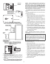
Thermostat Control Input Screen —
The Thermo-
stat Control Input Display is used to display the input status of
equipment requests from the thermostat (TSTAT). See Table 8.
Alarm Service Configuration Screen —
The Alarm
Service Configuration is used to configure the alarms used on
the PremierLink™ controller. See Table 9.
ALARM ROUTING CONTROL — The Alarm Routing
Control indicates which CCN system software or devices will
receive and process alarms sent by the PremierLink controller.
This decision consists of eight digits which can be set to zero or
one. A setting of one indicates alarms should be sent to this
device. A setting of zero disables alarm processing for that
device. Currently the corresponding digits are configured for
the following devices: first digit is for user interface software
(ComfortWORKS
®
, ComfortVIEW™, etc.); second digit is
for Autodial Gateway or Telink; fourth digit is for Alarm Print-
er Interface Module, DataLINK™ module; digits 3 and 5
through 8 are unused.
Alarm Routing
Control: Range: 00000000 to 1111111
Default Value: 00000000