


26
START-UP
Use the Carrier network communication software to start up
and configure the PremierLink™ controller.
Changes can be made using the ComfortWORKS
®
soft-
ware, ComfortVIEW™ software, or Network Service Tool.
The Network Service Tool is a portable interface device that
allows the user to change system set-up and set points from a
zone sensor or terminal control module. During start-up, the
Carrier software can also be used to verify communication
with PremierLink controller.
NOTE: All set-up and set point configurations are factory-
set and field-adjustable.
For specific operating instructions, refer to the literature
provided with user interface software.
Perform System
Check-Out
1. Check correctness and tightness of all power and
communication connections.
2. At the unit, check fan and system controls for proper
operation.
3. At the unit, check electrical system and connections of
any optional electric heat.
NOTE: If optional electric heat is installed, Heat Type
must be changed to “1” (electric heat) from default of “0”
(gas heat).
4. Check to be sure the area around the unit is clear of
construction dirt and debris.
5. Check that final filters are installed in the unit. Dust and
debris can adversely affect system operation.
6. Verify that the PremierLink controls are properly
connected to the CCN bus.
Initial Operation and Test —
Perform the following
procedure:
1. Apply 24 vac power to the control.
2. Connect the Service Tool to the phone jack service port of
the controller.
3. Using the Service Tool, upload the controller from
address 0, 31 at 9600 baud rate. The address may be set at
this time. Make sure that Service Tool is connected to
only one unit when changing the address.
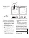
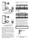
MEMORY RESET — DIP switch 4 causes a non-volatile
(E-squared) memory reset to factory defaults after the switch
has been moved from position 0 to position 1 and the power
has been restored. To enable the feature again, the switch must
be put back to the 0 position and power must be restored; this
prevents subsequent resets to factory defaults if the switch is
left at position 1.
To cause a reset of the non-volatile memory (to factory
defaults), turn the controller power off if it is on, move the
switch from position 1 to position 0, and then apply power to
the controller for a minimum of 5 seconds. At this point, no
action occurs, but the controller is now ready for the memory
to reset. Remove power to the controller again and move the
switch from position 0 to position 1. This time, when power is
applied, the memory will reset to factory defaults. The control-
ler address will return to bus 0 element 31, indicating that
memory reset occurred.
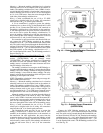
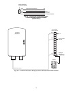
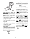
Install Navigator™ Display Module —
The Navi-
gator is a portable display module that conforms to NEMA 4
specifications for outdoor use in temperatures ranging from
–22 F (–30 C) to 158 F (70 C). The Navigator can be used
to configure and perform service diagnostics on machines
equipped with the PremierLink Controller. See Fig. 31.
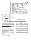
The Navigator keypad contains eleven menu LEDs and one
Alarm Status LED, all of which are red. The Navigator is capa-
ble of displaying four 24-character lines of information on a
backlit liquid crystal display. The Navigator has four functional
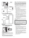
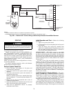
The unit must be electrically grounded in accordance with
local codes and NEC ANSI/NFPA 70 (American National
Standards Institute/National Fire Protection Association).
4
3
5
2
8
6
7
1
10
11
9
12
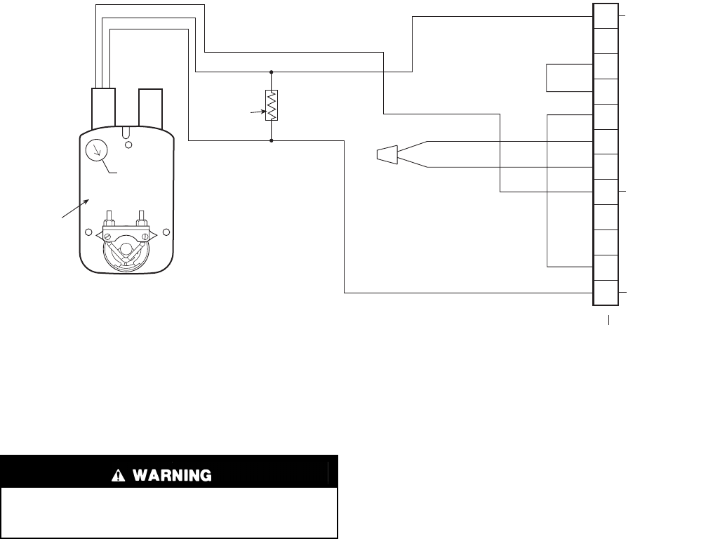
PINK
VIOLET
BLACK
BLUE
YELLOW
NOTE 1
NOTE 2
RUN
500 OHM
RESISTOR
50HJ540573
ACTUATOR
ASSEMBLY
RED
WHITE
ECONOMISER2 PLUG
DIRECT DRIVE
ACTUATOR
4-20 mA TO J9 ON
PREMIERLINK
BOARD
24 VAC
TRANSFORMER
GROUND
WIRES FOR
OAT SENSOR
4-20 mA SIGNAL
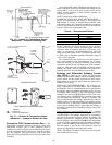
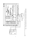
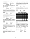
NOTES:
1. Switch on actuator must be in run position for economizer to operate.
2. 50HJ540573 actuator consists of the 50HJ540567 actuator and a harness with 500-ohm resistor.
Fig. 30B — PremierLink™ Control Wiring to Belimo-Style Actuator EconoMi$er2 Harness