


&-jQ
-
13
a--
4
IN/4
OUT
SWITCH
MODULE
,-
-
m
-
-
-
-f-J
J7-10
,~,.
$$
&
i-
-
___
-
_-a
J7-lf
c,:
*
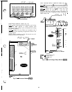
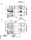
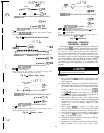
30GN040-210
AND ASSOCIATED MODULAR UNITS
----
1
-El
TB-11
--a-
-0
2
TBI1
30GT225,250,280
FLOTRONIC’” II UNITS
TB
-
Terminal Block
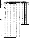
NOTE: The
30GT225,250,280
Flotronic II units require the acces-
sory options module for this feature
Fig. 33
-
Remote Dual Set Point Control
43
7
6
1
------
cl-
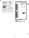
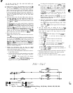
CWP
-----
-cl
3
-rB$J
115/23ovv
f
-------_--
__--
4
-t-l
T5-3
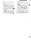
30GN040-210
AND ASSOClATED MODULAR UNITS
--v-w
3
El
TE5
WI--
u
4 TE5
30GT225,250,280
FLOTRONIC II UNITS
CWP
-
Chilled Water Pump
TB
-
Terminal Block
NOTE: The maximum load allowed for the chilled water pump circuit
is 125 va sealed, 1250 va inrush at 115 or 230 v
Fig. 34
-
Chilled Water Pump
-43
77
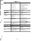
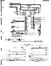
ALARM SHUTOFF
SWITCH
I-
-------a---
-cl
1 TB-3
I
i
L
------2
T8-3
cl
30GN040-210
AND ASSOCIATED MODULAR UNITS
_d--
----
u
2 TB-5
30GT225,250,280
FLOTRONIC II UNITS
TB
-
Terminal Block
NOTE: The maximum load allowed for the alarm circuit is 125 va
sealed, 1250 va inrush at 115 or 230 v
Fig. 35
-
Remote Alarm
73
-43
-78
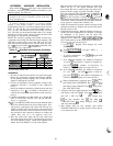
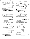
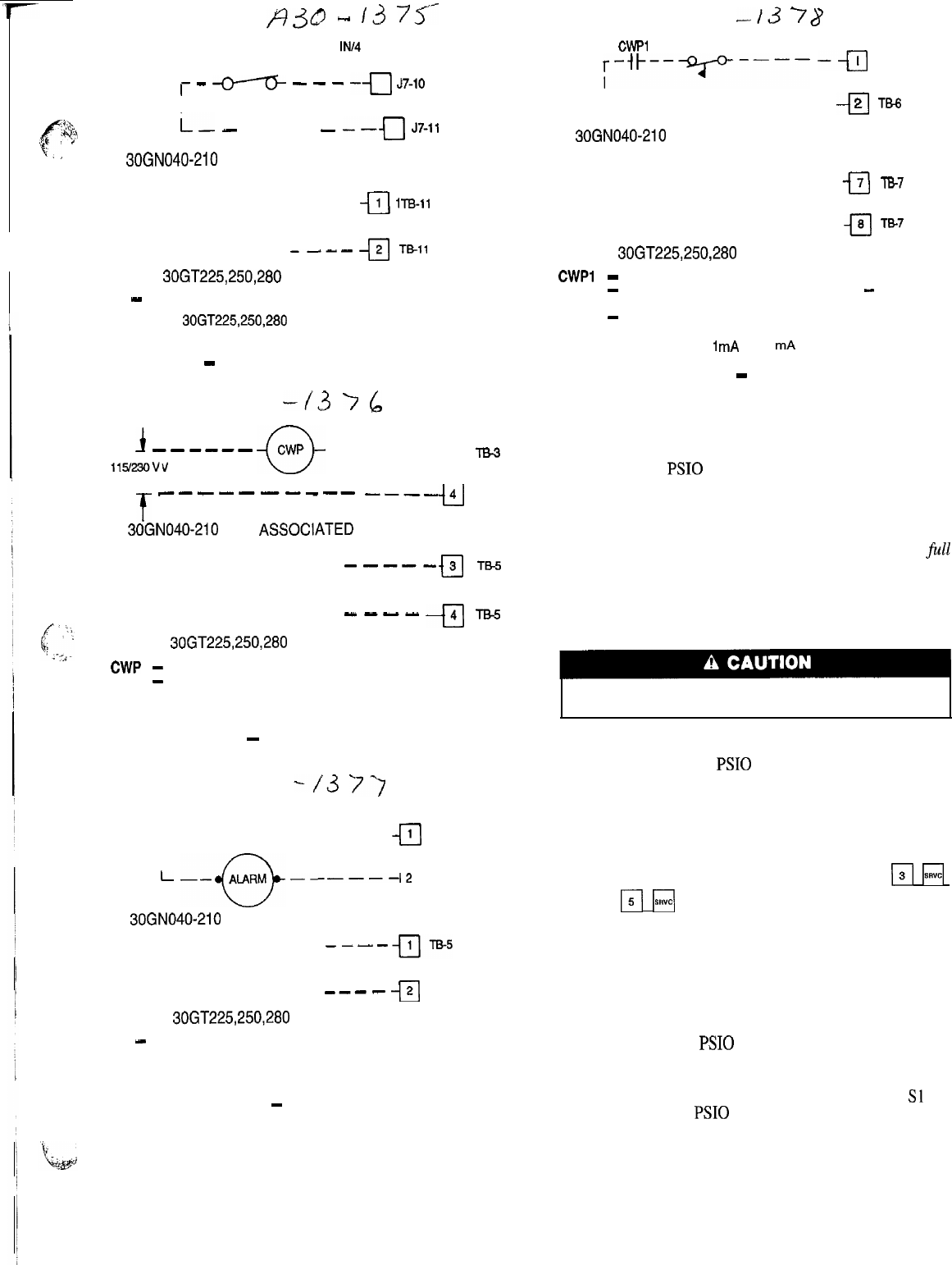
CWPl (CWFS)
;-+--y----
--a
TB-6
I-------
------
-cl
2
TB-6
30GN040-210
AND ASSOCIATED MODULAR UNITS
-----
-El
7
TB-7
-----
u
8 TE7
30GT225,250,280 FLOTRONIC I I UN ITS
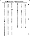
CWPI
-
Chilled Water Pump Interlock
CWFS
-
Chilled Water Flow Switch (not required
-
low flow
protection is provided by Flotronic II controls)
TB
-
Terminal Block
NOTE: Contacts must be rated for dry circuit application, capable of
reliably switching a 5 vdc,
1
mA
to 20
mA
load.
Fig. 36
-
Interlocks
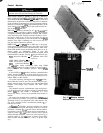
REPLACING DEFECTIVE
PROCESSOR MODULE
The replacement part number is printed on a small label
on front of the PSI0 module. The model and serial num-
bers are printed on the unit nameplate located on an exte-
rior corner post. The proper software and unit configuration
data is factory installed by Carrier in the replacement mod-
ule. Therefore, when ordering a replacement processor mod-
ule (PSIO), specify complete replacement part number, full
unit model number, and serial number. If these numbers
are not provided, the replacement module order is config-
ured instead as a generic Flotronic’” 11 replacement mod-
ule. This requires reconfiguration of the module by the
installer.
Electrical shock can cause personal injury, Disconnect
all electrical power before servicing.
Installation
1.
2.
3.
4.
5.
6.
7.
Verify the existing PSI0 module is defective by using
the procedure described in the Control Modules sec-
tion on page 64.
Refer to Start-Up Checklist for Flotronic II Chiller Sys-
tems (completed at time of original start-up) found in
job folder. This information is needed later in this
procedure. If checklist does not exist, fill out the
ri
H
and
Fi
F\
configuration code sections on a new check-
list. Tailor the various options and configurations as
needed for this particular installation.
Check that all power to unit is off. Carefully discon-
nect all wires from defective module by unplugging the
6 connectors. It is not necessary to remove any of the
individual wires from the connectors. Remove the green
ground wire.
Remove defective
PSI0
by removing its mounting screws
with a Phillips screwdriver, and removing the module
from the control box, Save the screws for later use.
Use a small screwdriver to set address switches Sl and
S2 on the new PSI0 module to exactly match the set-
tings on the defective module.
Package the defective module in the carton of the new
module for return to Carrier.
Mount the new module in the unit control box using a
Phillips screwdriver and the screws saved in Step 4 above.