


n
POINT NUMBER OF
FIRST CHANNEL
Q
EKE
LIMIT
(ALARM CODE 312
(MODE
91
4 nw/4
OUJJU
PWR
I
--e-------1-
--
__-----a
---mm-
_------
__----.
__----
---
---se
___---c---
----
-
-
-
-
-
_
-
-
-
-
-
-
-
-
(MODE
71
‘-+p--------
f
----__e-
----
--
RFt!EF
(ALARM
COOE
21)
301
(MODE
El
__----a-
__----
LB---------
A
In
AOt
B
d
d
H
=
RET
I-
’
c
4
z
DO+
5
D
“1
rAO+
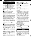
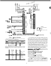
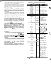
LEGEND
COMM
-
Communications Bus
PWR
-
Power
SW
-
Switch
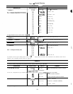
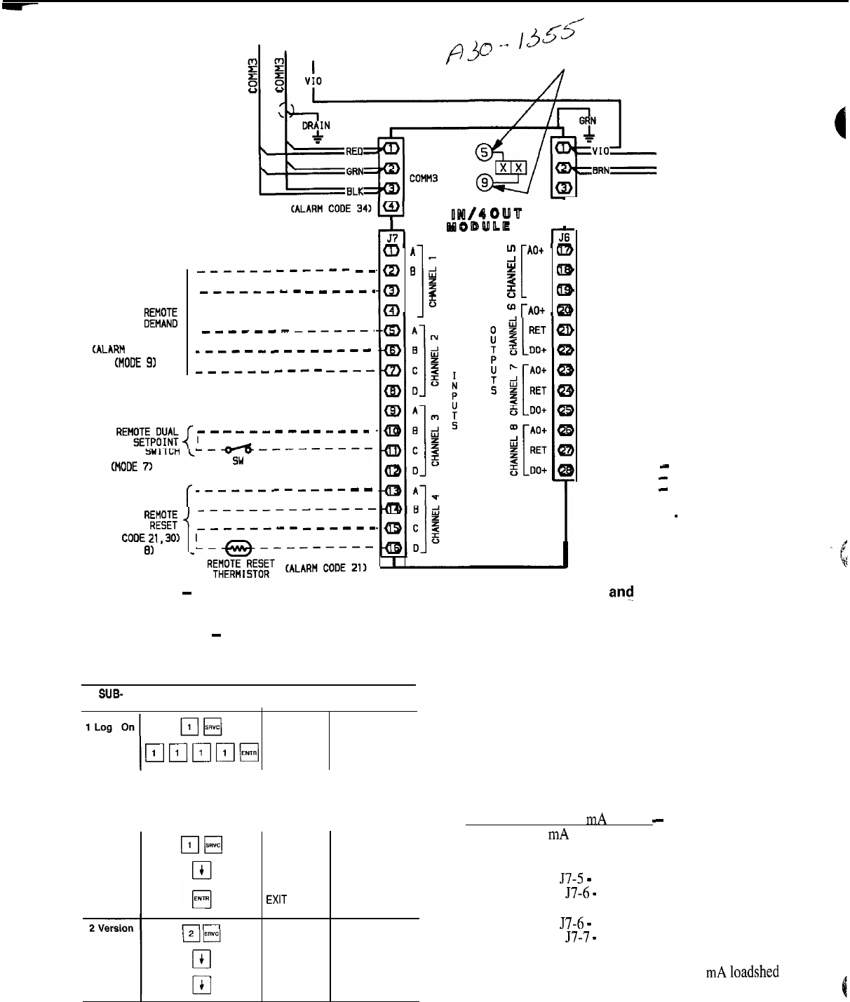
NOTE: For specific connection points,
see Fig. 24
-
29.
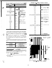
Fig 6
-
4 IN/4 OUT Options Module Wiring for Reset, Demand Limit, an! Dual Set Point
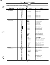
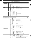
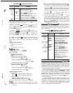
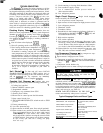
Table 11
-
Service Functions
To view and modify configurations, the password must
be entered under the log on subfunction.
SUB-
I
KEY FAD
FUNCTION ENTRY
DISPLAY
COMMENT
PASSWORD
Enter Password/
Disable Password
LOGGED ON Logged On
NOTE: Configurations may be modified at this time. When
finished viewing and/or modifying configurations, log out
as follows:
LOGGED ON
LOG OFF
EXIT
LOG
VERSION
xxxxxxxx
X
Disable Password
Protection
Logged Off/
Enable Password
Protection
Software
Information
Version No
of Software
Language Options
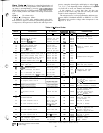
To use Demand Limit, first enable loadshed, then enter
demand limit set points. See Example 7A. Closing the first
stage demand limit contact puts unit on the first demand
limit level, that is, the unit does not exceed the percentage
of capacity entered as demand limit stage 1. Closing con-
tacts on second-stage demand limit relay prevents unit from
exceeding capacity entered as demand limit stage 2. The
demand limit stage that is set to the lowest demand takes
priority if both demand limit inputs are closed.
The demand limit function must be enabled in order to
function and may be turned off when its operation is not
desired. The demand limit relays can, in off condition, re-
main connected without affecting machine operation.
-Demand Limit, 4-20 mA Signal
-
The controls can also
accept a 4-20 mA signal for load shedding. Input for the
signal are terminals shown below:
Externally powered (loop isolator required)
Positive lead to
57-5
-
4 In/4 Out Module
Negative lead to 57-6
-
4 In/4 Out Module
Internally powered
Positive lead to J7-6
-
4 In/4 Out Module
Negative lead to 57-7
-
4 In/4 Out Module
See Field Wiring section on page 71 and Fig. 6.
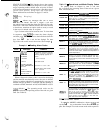
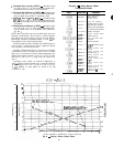
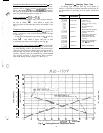
At field configuration step, select 4-20 mA
loadshed
by
entering q when the LSTYP 0 display appears. See
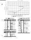
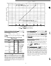
Example 7B. Then enter set points as follows. In this ex-
ample, set points are coordinates of the demand limit curve
shown in Fig. 8.
42