


Control Modules
Turn controller power off before servicing controls. This
ensures safety and prevents damage to controller.
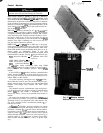
PROCESSOR MODULE (PSIO). 4 IN/4 OUT MODULE
(SIO), LOW-VOLTAGE TiELAY’MODULE (DSIO), AND
EXV DRIVER MODULE (DSIO)
-
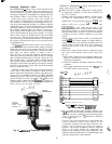
The PSIO, DSIO and
SIO modules all perform continuous diagnostic evaluations
of the condition of the hardware. Proper operation of these
modules is indicated by LEDs (light emitting diodes) on the
front surface of the DSIOs, and on the top horizontal sur-
face of the PSI0 and SIO.
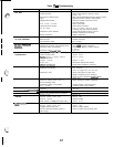
RED LED
-
Blinking continuously at a
3-
to
5-second
rate
indicates proper operation. Lighted continuously indicates
a problem requiring replacement of module. Off continu-
ously indicates power should be checked. If there is no in-
put power, check fuses. If fuse is bad, check for shorted
secondary of transformer or for bad module. On the PSI0
module, if the light is blinking at a rate of twice per sec-
ond, the module should be replaced.
GREEN LED
-
On a PSI0 and an SIO, this is the green
LED closest to COMM connectors. The other green LED
on module indicates external communications, when used.
Green LED should always be blinking when power is on. It
indicates modules are communicating properly. If green LED
is not blinking, check red LED. If red LED is normal, check
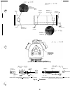
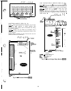
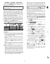
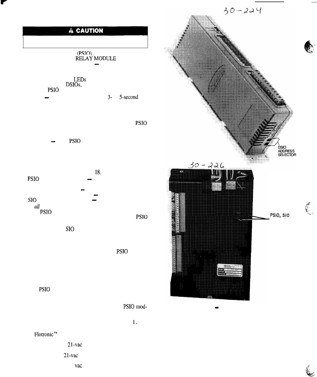
module address switches. See Fig.
18,
Proper addresses are:
PSI0 (Processor Module)
-
01 (different when CCN
connected)
DSIO (Relay Module)
-
19
DSIO (EXV Driver Module)
-
31
SIO (4 In/4 Out Module)
-
59
If
all
modules indicate communication failure, check COMM
plug on PSI0 module for proper seating. If a good connec-
tion is assured and condition persists, replace PSI0
module.
If only DSIO or SIO module indicates communication
failure, check COMM plug on that mode for proper seat-
ing. If a good connection is assured and condition persists,
replace DSIO or SIO module.
All system operating intelligence rests in PSI0 module ,
the module that controls unit. This module monitors con-
ditions through input and output ports and through DSIO
modules (low-voltage relay module and EXV driver
module).
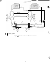
The machine operator communicates with microproces-
sor through keypad and display module. Communication
between
PSI0
and other modules is accomplished by a 3-wire
sensor bus. These 3 wires run in parallel from module to
module.
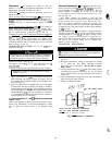
On sensor bus terminal strips, terminal 1 of PSI0
mod-
Module Address
ule is connected to terminal 1 of each of the other modules.
Fig. 18
-
Selector Switch Locations
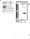
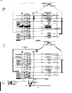
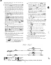
Terminals 2 and 3 are connected in the same manner. See
Fig, 19, If a terminal 2 wire is connected to terminal
1,
sys-
tem does not work.
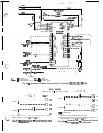
In
FlotronicTM
II Chillers, processor module, low-voltage
relay module, and keypad and display module are all pow-
ered from a common 21-vat power source which connects
to terminals 1 and 2 of power input strip on each module. A
separate source of 21-vat power is used to power options
module through terminals 1 and 2 on power input strip. A
separate source of 12.5 vat power is used to power EXV
driver module through terminals 1 and 2 on power input
strip.
PSIO,
SIO
ADDRESS
SELECTOR
64