


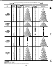
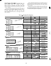
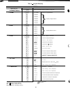
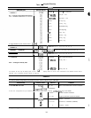
Table 9
-
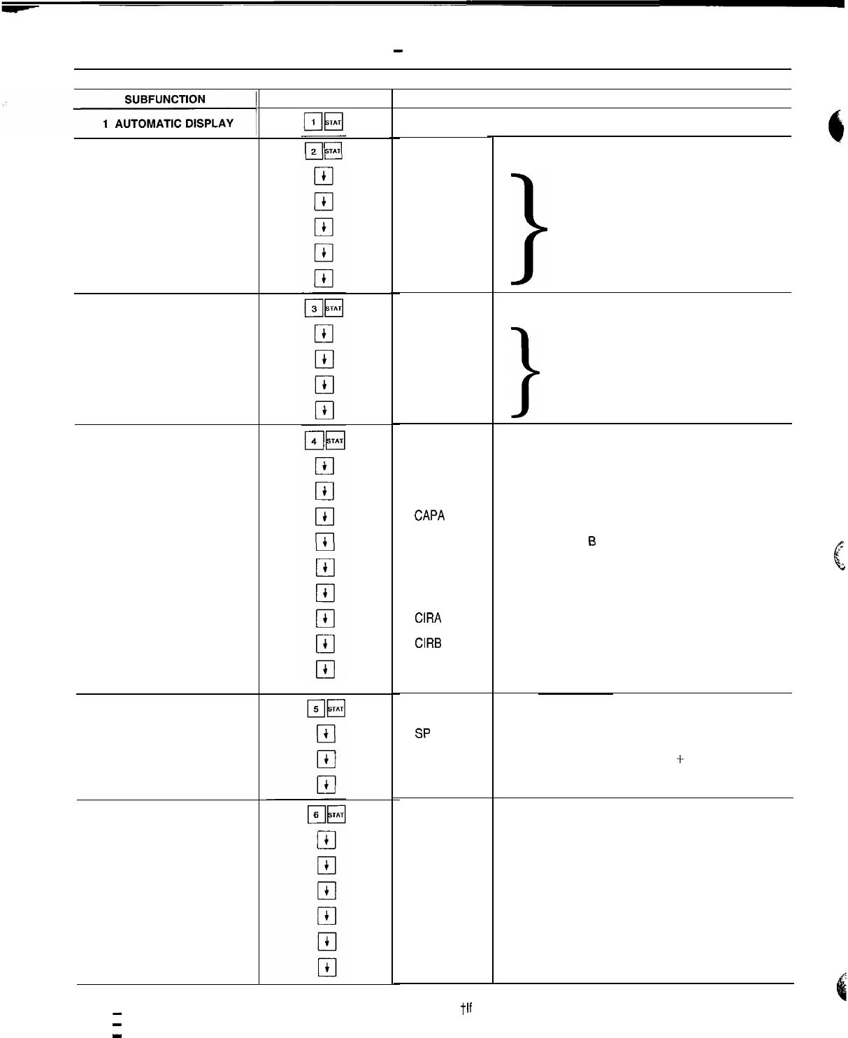
Keypad Directory
STATUS
2 ALARMS
I
3 MODES
4 STAGE
5 SET POINT
6 TEMPERATURE
KEYPAD ENTRY
DISPLAY 1
LEGEND
CCN
-
Carrier Comfort Network
EXV
-
Electronic Expansion Valve
MOP
-
Maximum Operating Pressure
COMMENT
Refer to Automatic Display Operation on page 28
X ALARMS
ALARM X
ALARM X
ALARM X
ALARM X
ALARM X
X MODES
MODE X
MODE X
MODE X
MODE X
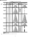
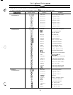
STAGE
STAGE X
CAPT X
CAPA X
CAP0 X
LMT X*
LOAD X*
CIRA X
CIRB X
SMZ X
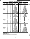
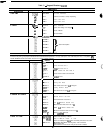
SET POINT
SP
x
MSP X
TWX
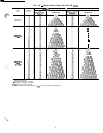
TEMPS
EWTX
LWT X
SCTA X
SSTA X
CTA X
SHA X
Number of Tripped Alarms
>
Displays Tripped Alarms
Number of Modes in Effect
>
Displays Mode in Effect
Capacity Staging Information
Number of Requested Stages
Percent of Total Capacity
Percent Circuit A Capacity
Percent Circuit 6 Capacity
Demand Limit Set Point
Load Limit Set Point
Circuit A Compressor Relay Status
Circuit B Compressor Relay Status
Load/Unload Factor for Compressors
Factor = 1 Unloader Factor = 0 6
;,;
6
Fluid Set Point Information
Set Point
Modified Set Point = Set Point + Reset
Cooler Leaving Fluid Temperature
Temperature Information
Cooler Entering Fluid Temperature
Cooler Leaving Fluid Temperature
Circuit A Saturated Condenser Temperature
Circuit A Saturated Suction Temperature
Compressor Al Suction Temperature
Circuit A Suction Superheat
*Must be configured
j-If applicable
30