


G
Y
040-420
Contrc
with
h
_.-
-
v----w
I
CONTENTS
Page
SAFETY CONSIDERATIONS . . .
+
. . . . ,
e
+.
. , . . , .
1
GENERAL . . . . . . , . . . . , . , . . . , . , . . . . , . , . . . . . . . . 2
MAJOR SYSTEM COMPONENTS . . . . . . . . . . . . 2-4
Processor Module
. . . . . . . . . . . . . . . . . . . . . . . . ...2
Low-Voltage Relay Module . , . . . . . . , . , . , , . . . . . 2
Electronic Expansion Valve Module . . . . . . . . . . . 2
Options Module . . . . . . . . . . . . . . . . *. . . . . . . . . . . . 2
Keypad and Display Module
(Also Called
HSIO
or LID)
. . . . . . . . . . . . . . . . . . 2
Control Switch .
+
. . . , . . . . . . . . . . . . . . . . . . . . . . . . 2
Electronic Expansion Valve (EXV) . . . , . . . . . . . . 4
Sensors . . . . . . . . . . . . . . . . . . . . . . . . . . . . . . . . . . ...4
Compressor Protection Control
Module (CPCS) . . , . . . . . . . . . . . . . . . . . . . . . . . . . 4
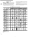
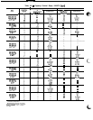
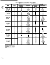
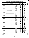
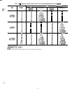
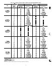
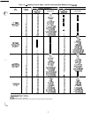
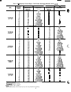
OPERATION DATA . . . . . . . . . . . . . , . . . . , .
+
. . . , 5-47
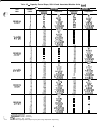
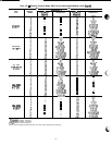
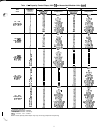
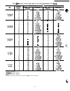
Capacity Control . . . . , , . . . . . . . . . . . . . . . . . .
+
. . . . 5
Head Pressure Control . .
1
. . . . .
+
. . . . . . . . . . . . . 26
Pumpout
. . . . . . . . . . . . . . . . . . . . . . . . . . . . . . . . ...27
Keypad and Display Module
(Also Called
HSIO
or
LID)
28
ACCESSING FUNCTIONS AND :tiBFtiN?TI’dNS
SUMMARY DISPLAY
KEYPAD OPERATING INSTRUCTIONS
STATUS FUNCTION
TEST FUNCTION
HISTORY FUNCTION
SET POINT FUNCTION
SERVICE FUNCTION
SCHEDULE FUNCTION
TROUBLESHOOTING
......................
48-67
Checking Display Codes
.....................
48
Unit Shutoff
................................ 48
Complete Unit Stoppage
....................
48
Single Circuit Stoppage
.....................
48
Lag Compressor Stoppage .................. 48
SAFETY CONSIDERATIONS
Installing, starting up, and servicing this equipment can
be hazardous due to system pressures, electrical compo-
nents, and equipment location (roof, elevated structures, etc.).
Only trained, qualified installers and service mechanics should
install, start-up, and service this equipment.
When working on this equipment, observe precautions in
the literature, and on tags, stickers, and labels attached to
the equipment, and any other safety precautions that apply.
Follow all safety codes. Wear safety glasses and work gloves.
Use care in handling, rigging, and setting this equipment,
and in handling all electrical components.
Page
Restart Procedure . . . . . . . . . . . . . . . . . . . . . . . ...48
l POWER FAILURE EXTERNAL TO THE UNIT
Alarm Codes
. . . . . . , . . . . . . . , . . . . . . . . . . , . . . . . 49
Compressor Alarm Circuit . . . . .
e
+.
. . . . . . . . . . .
50
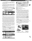
Electronic Expansion Valve . . . . . . . . . . . . . . . . , . 56
l EXV OPERATION
l CHECKOUT PROCEDURE
Thermistors . . . . . . . . . . . . . . . . . . . . . . . . . . . . . ...60
a LOCATION
l THERMISTOR REPLACEMENT (Tl, T2, T7, T8)
(Compressor and Cooler)
Pressure Transducers . . . , . . . , . . . . . .
+
. . .
+
. . . . 60
l TROUBLESHOOTING
l TRANSDUCER REPLACEMENT
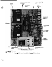
Control Modules . . . . . . . . . . . . . . . . . . . . . . . , . . . . 64
l PROCESSOR MODULE (PSIO), 4IN/40UT
MODULE (SIO), LOW-VOLTAGE RELAY
MODULE (DSIO), AND EXV DRIVER MODULE
(DSIO)
. RED LED
l GREEN LED
l PROCESSOR MODULE (PSIO)
l LOW-VOLTAGE RELAY MODULE (DSIO)
. 4IN/40UT MODULE (SIO)
ACCESSORY UNLOADER INSTALLATION
68-7 1
Installation . . . . . . . , . . .
s
. . . , . . . .
s
. . . . . . . .
.‘.‘.
. 68
l 040-110, 130 (60 Hz) UNITS
(and associated modular units)
l 130 (50 Hz), 150-210, 225, 250, and 280 UNITS
(and associated modular units)
FIELD WIRING . . . . . . . . . . . . , . . . . . . . . . . . . . . . 71-73
REPLACING DEFECTIVE PROCESSOR
MODULE (PSIO)
. . . .
+
s
. . . . . . .
+
. . . . . .
*
.
+
.
73,74
Installation . . . . . . . . . . . . . . . . . . . . . . . . . . . . . . ...73
Electrical shock can cause personal injury and death.
Shut off all power to this equipment during installation
and service. There may be more than one disconnect
switch. Tag all disconnect locations to alert others not
This unit uses a microprocessor-based electronic con-
trol system. Do not use jumpers or other tools to short
out components, or to bypass or otherwise depart from
recommended procedures. Any short-to-ground of the
control board or accompanying wiring may destroy the
electronic modules or electrical components.
Manufacturer reserves the right to discontinue, or change at any time, specifications or designs without notice and without incurring obligations.
Book 2
--I-
PC 903
Catalog No. 563-015 Printed in
U
S A.
Form
30GN-2T
pg
1
1-94 Replaces: 30GB,GT-1 T,
Tab 5c
30GN-1T