


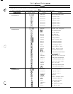
Table 9
-
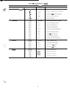
Keypad Directory (cant)
SERVICE (cord)
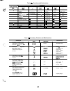
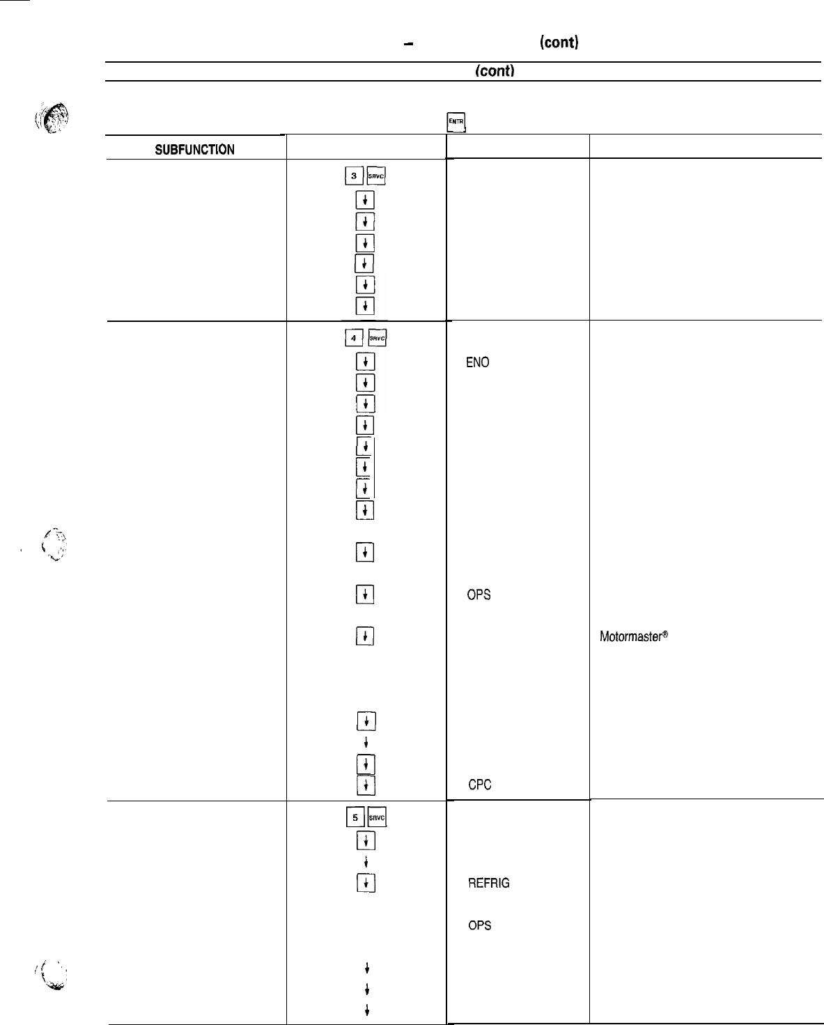
The next 3 subfunctions provide the ability to modify configurations Refer to separate Installation, Start-Up, and Service Instructions
supplied with unit for further information on changing configurations.
To change a configuration, enter the new configuration and press
4
while on the correct configuration.
F.-’
SUBFUNCTiON
i
j,
I’
.
Fc,s;B,:
3 FACTORY
CONFIGURATION
4 FIELD
CONFIGURATION
5 SERVICE
CONFIGURATION
KEYPAD ENTRY
Cl
t
Cl
t
c
t
c
t
[I
t
cl
t
cl
t
0
t
q
t
0
t
a
t
Cl
t
cl
t
cl
t
q
t
cl
t
cl
+
Cl
+
Cl
t
p-&q
cl
t
cl
t
Cl
t
cl
t
cl
t
cl
t
cl
+
q
t
cl
t
DISPLAY COMMENT
FACT CFG
xxxxxxxx
xxxxxxxx
xxxxxxxx
xxxxxxxx
xxxxxxxx
xxxxxxxx
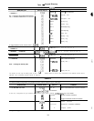
Factory Configuration Codes
Configuration Code 1
Configuration Code 2
Configuration Code 3
Configuration Code 4
Configuration Code 5
Configuration Code 6
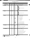
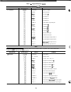
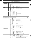
FLD CFG
EN0 X
BUS X
BAUD X
FLUID X
UNITS X
LANG X
NULA X
NULB X
HGB X
SEQT X
SEQF X
OPS
x
HEADM X
MM X
CSPTYP X
CRTYP X
ERTYP X
LSTYP X
RAMP X
LOCK X
CPC
x
Adjustable Field Configuration
CCN Element Address
CCN Bus Number
CCN Baud Rate
Cooler Fluid Select
Display Unit Select
Display Language Select
No Circuit A Unloaders
No. Circuit B Unloaders
Hot Gas Bypass Select
Loading Sequence Select
Lead/Lag Sequence Select
Oil Pressure Switch Select
Head Pressure Control Method
Motormaster@
Select
Cooling Set Point Control Select
Cooling Reset Control Select
External Reset Sensor Select
Demand Limit Control Select
Ramp Load Select
Cooler Pump Interlock Select
Cooler Pump Control Select
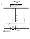
SRV CFG
xxxxxxxx
xxxxxxxx
REFRIG X
TDTYP X
OPS
x
LPS x
FANTYP X
SH X
MOP X
Service Configurations
Configuration Code 7
Configuration Code 8
Refrigerant
Pressure Transducer Select
Oil Transducer Set Point
Low Pressure Set Point
Fan Staging Select
EXV Superheat Set Point
EXV MOP Set Point
35