


PSI0
DSIO DSIO
HSIO
SIO
(
pRocEMssOp
(RELAY)
(EXV
DRIVER)
(LID) (4
I;W;UT
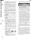
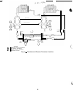
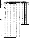
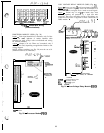
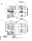
Fig.
19
-
Sensor Bus Wiring
(Communications)
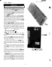
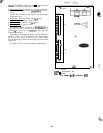
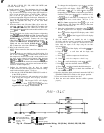
PROCESSOR MODULE (PSIO) (Fig. 20)
Inputs
-
Each input channel has 3 terminals; only 2 of the
terminals are
used.
Application of machine determines which
terminals are used. Always refer to individual unit wiring
for terminal numbers.
Outputs
-
Output is 24 vdc. There are 3 terminals, only 2
of which are used, depending on application. Refer to unit
wiring diagram.
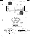
NOTE: Address switches (see Fig. 20) must be set at 01
(different when CCN connected).
fL.w--
6%2
0
P-
CHASSIS
GROUND
I
P
0
PWR
-
Power
ADDRESS
<
0
SWITCHES
0
PSI0
I-
-( REAR)
NETWORK
SNNECTOR
’ (FORWARD)
SENSOR BUS
CONNECTOR
J8
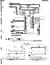
Fig. 20
-
Processor Module
(PSIO)
65
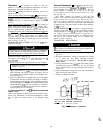
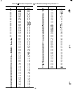
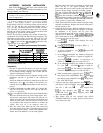
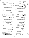
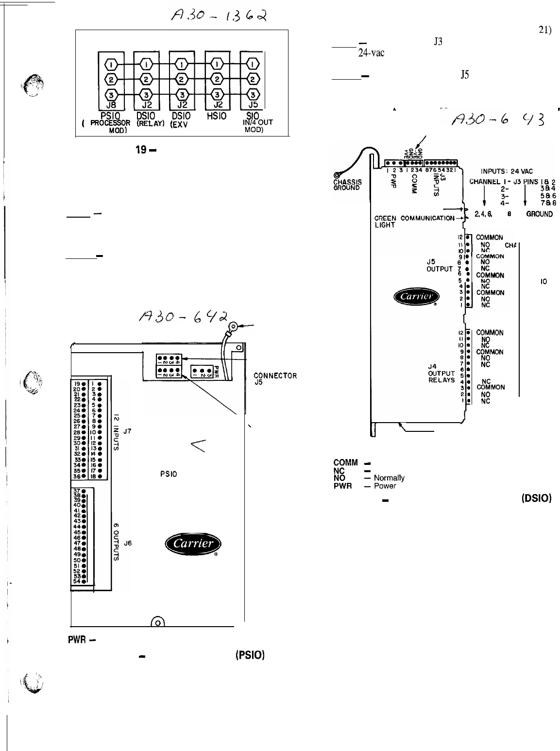
LOW VOLTAGE RELAY MODULE (DSIO) (Fig. 21)
Inputs
-
Inputs on strip
53
are discrete inputs (ON/OFF).
When
24vat
power is applied across the 2 terminals in a
channel it reads as on signal. Zero v reads as an off signal.
Outputs
-
Terminal strips J4 and JS are internal relays whose
coils are powered-up and powered-off by a signal from micro-
processor. The relays switch the circuit to which they are
connected. No power is supplied to these connections by
DSIO module.
L
--/%o-6
93
-
SENSOR BUS CONNECTOR
/
RED STATUS LIGHT
-
b
1
$i
1
!;i
2,4,6,
AND 8 ARE GRQUND (C)
9e
ZTPUT
“7
:
I
RELAYS
“,
:
I
%YoN
C&MON
2:
COMMON
NO
&MON
2:
NEL I2
I I
IO
9
8
7
6
5
/
7
ADDRESS ADJUSTMENT
(NOT SHOWN) ON UNDERSIDE
LEGEND
ii!“”
-
Communications Bus
-
Normally Closed
I%
1
bb;n$ly Open
Fig. 21
-
Low-Voltage Relay Module
(DSIO)