


-%a-
GENERAL
IMPORTANT: This publication contains controls, op-
eration and troubleshooting data for 3OGNO40-420 and
30GT225, 250, and 280
FlotronicTM
II chillers,
Circuits are identified as circuits A and B, and com-
pressors are identified as Al, A2, etc. in circuit A,
and
BI,
B2, etc. in circuit B.
Use this guide in conjunction with separate Instal-
lation Instructions booklet packaged with the
unit,
The 30G Series standard Flotronic II chillers feature
microprocessor-based electronic controls and an electronic
expansion valve (EXV) in each refrigeration circuit.
NOTE: The 30GN040 and 045 chillers with a
factory-
installed brine option have thermal expansion valves (TXV)
instead of the EXV.
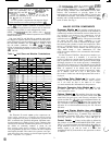
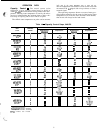
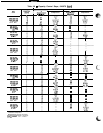
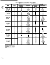
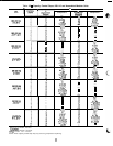
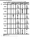
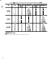
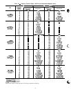
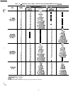
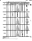
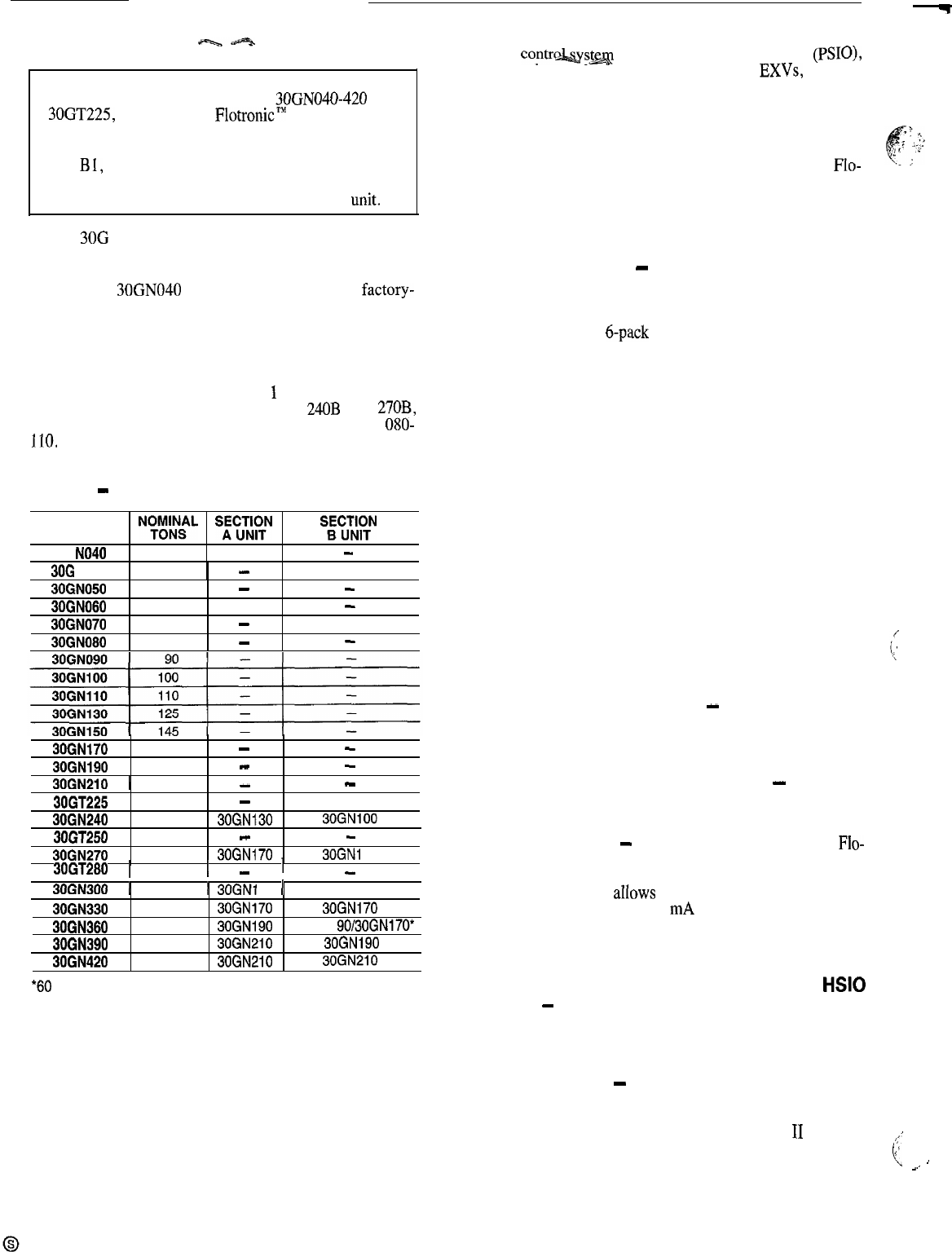
Unit sizes 240,270, and 300-420 are modular units which
are shipped as separate sections (modules A and B). Instal-
lation instructions specific to these units are shipped inside
the individual modules. See Table
1
for a listing of unit
sizes and modular combinations. For modules 24OB and
270B,
follow all general instructions as noted for unit sizes
OSO-
110.
For all remaining modules, follow instructions for unit
sizes 130-210.
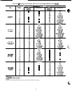
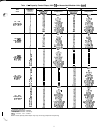
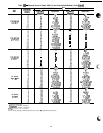
Table 1
-
Unit Sizes and Modular Combinations
UNIT MODEL
NoT”o’NNs”L
SE\WlK&N
ssE%~N
30G NO40 40
-
3OG NO45
45
-
30GN050
50
-
-
30EN060 60
-
-
30GN070
70
-
30GN080 80
- -
30GNlfO 160
- -
30GN190
180
-
-
30GN210
1 200 I
-
I
-
30GT225
225
-
30GN240 225 30GN130
30GNlOO
30GT250
250
-
-
30GN270 260 30QN170
30GNi
00
30GT280 1
280
1
-
I
-
30GN300 1 285 1
30GNi
30 1 30GNf 70
_...---
30GN330
325
30GNl70
30GN170
30GN360
350 30GN190 30GNf 90/30GN170*
30GN390
380 30GN210
30GN190
30GN420
400 30GN210
30GN210
*60 Hz units/50 Hz units.
The Flotronic II control system cycles compressor un-
loaders and/or compressors to maintain the selected leaving
water temperature set point. It automatically positions the
EXV to maintain the specified refrigerant superheat enter-
ing the compressor cylinders. It also cycles condenser fans
on and off to maintain suitable head pressure for each cir-
cuit. Safeties are continuously monitored to prevent the unit
from operating under unsafe conditions. A scheduling func-
tion, programmed by the user, controls the unit occupied/
unoccupied schedule. The control also operates a test pro-
gram that allows the operator to check output signals and
ensure components are operable.
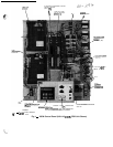
The
contrwsm
consists of a processor module (PSIO)9
a low-voltage relay module (DSIO-LV), 2
EXVs,
an EXV
driver module (DSIO-EXV), a 6-pack relay board, a key-
pad and display module (also called HSIO or LID), ther-
mistors, and transducers to provide inputs to the
microprocessor. An options module (SIO) is used to pro-
vide additional functions. This module is standard on 30GN
modules and is a field-installed accessory on the 30GT
Flo-
tronic II units. See Fig. 1.
MAJOR SYSTEM COMPONENTS
Processor Module
-
This module contains the oper-
ating software and controls the operation of the machine. It
continuously monitors information received from the vari-
ous transducers and thermistors and communicates with the
relay modules and
&pack
relay board to increase or de-
crease the active stages of capacity. The processor module
also controls the EXV driver module, commanding it to open
or close each EXV in order to maintain the proper super-
heat entering the cylinders of each lead compressor. Infor-
mation is transmitted between the processor module and re-
lay module, the EXV driver module, and the keypad and
display module through a 3-wire communications bus. When
used, the options module is also connected to the commu-
nications bus.
For the Flotronic II chillers, the processor monitors sys-
tem pressure by means of 6 transducers, 3 in each lead com-
pressor. Compressor suction pressure, discharge pressure,
and oil pressure are sensed. If the processor senses high
discharge pressure or low suction pressure, it immediately
shuts down all compressors in the affected circuit. During
operation, if low oil pressure is sensed for longer than one
minute, all compressors in the affected circuit are shut down.
At start-up, the coil pressure signal is ignored for 2 min-
utes. If shutdown occurs due to any of these pressure faults,
the circuit is locked out and the appropriate fault code is
displayed.
Low-Voltage Relay Module
-
This module closes
contacts to energize compressor unloaders and/or compres-
sors. It also senses the status of the safeties for all compres-
sors and transmits this information to the processor.
Electronic Expansion Valve Module
-
This mod-
ule receives signals from the processor and operates the elec-
tronic expansion valves.
Options Module
-
This module allows the use of
Flo-
tronic II features such as dual set point, remote reset, de-
mand limit, hot gas bypass, and accessory unloaders. The
options module also
aIlows
for reset and demand limit to be
activated from a remote 4-20 mA signal. The options mod-
ule is installed at the factory on 040-210 and modular 240-
420 units. It is a field-installed accessory for 225, 250 and
280 units.
Keypad and Display Module (also called HSlO
or LID)
-
This device consists of a keypad with 6 func-
tion keys, 5 operative keys, 12 numeric keys, and an al-
phanumeric g-character LCD. Key usage is explained in
Accessing Functions and Subfunctions section
on
page 28.
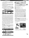
Control Switch
-
Control of the chiller is defined by
the position of the LOCAL/ENABLE-STOP-CCN switch.
This is a 3-position manual switch that allows the chiller to
be put under the control of its own Flotronic II controls,
,,
manually stopped, or put under the control of a Carrier Corn-
:f
fort Network (CCN), Switch allows unit operation as shown
c
’
_.
’
in Table 2.
2