


TROUBLESHOOTING
The
FlotronicTY
II control has many features to aid the
technicians in troubleshooting a Flotronic II Chiller. By us-
ing keypad and display module and status function, actual
operating conditions of the chiller are displayed while unit
is running. Test function allows proper operation of com-
pressors, compressor unloaders, fans,
EXVs
and other com-
ponents to be checked while chiller is stopped. Service function
displays how configurable items are configured. If an op-
erating fault is detected, an alarm is generated and an
alarm code(s) is displayed under the subfunction
m
I;;;;]
,
along with an explanation of the fault. Up to 5 current alarm
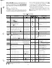
codes are stored. For checking specific items, see Table 9.
Checking Display Codes
-
To determine how ma-
chine has been programmed to operate, check diagnostic
information
((
w
)
and operating mode displays
(/
Fi
).
If no
dismay
annears,
follow procedures in Control Mod-
ules
section+onlpage
64. If display is working, continue as
follows:
1.
Note all alarm codes displayed,
F\
bi
.
2. Note all operating mode codes displayed,
MH
.
3. Note leaving chilled water temperature set point in ef-
fect and current leaving water temperature,
MFI
.
If machine is running, compare the “in effect” leaving
water temperature set point with current water tempera-
ture. Remember, if reset is in effect, the values may be
different because machine is operating to the modified
chilled water set point, If current temperature is equal to
set point, but set point is not the one desired, remember
that if dual set point has been selected in the schedule
function, there are 2 set points to which the machine can
be operating. Check the programming of schedule func-
tion
to
see if occupied or unoccupied set point should be
in effect.
Unit Shutoff
-
To shut unit off, move LOCAL/
ENABLE-STOP-CCN Switch to STOP position. Any re-
frigeration circuit operating at this time continues to com-
plete the pumpout cycle. Lag compressors stop immediately,
and lead compressors run to complete
pumpout.
Complete Unit Stoppage
-
Complete unit stop-
page can be caused by any of the following conditions:
1. Cooling load satisfied
1
2. Remote ON/OFF contacts open
3. Programmed schedule
4. Emergency stop command from CCN
5. General power failure
6. Blown fuse in control power feed disconnect
7. Open control circuit fuse
8. LOCAL/ENABLE-STOP-CCN switch moved to STOP
position
9. Freeze protection trip
10. Low flow protection trip
11. Open contacts in chilled water flow switch (optional)
12. Open contacts in any auxiliary interlock. Terminals that
are jumpered from factory are in series with control
switch. Opening the circuit between these terminals places
unit in stop mode, similar to moving the control switch
to STOP position. Unit cannot start if these contacts
are open. If they open while unit is running, unit pumps
down and stops.
48
13. Cooler entering or leaving fluid thermistor failure
14. Low transducer supply voltage
15. Loss of communications between processor module and
other control modules
16. Low refrigerant pressure
Single Circuit Stoppage
-
Single circuit stoppage
can be caused by the following:
1
Low oil pressure in lead compressor
2. Open contacts in lead compressor high-pressure switch
3. Low refrigerant pressure
4. Thermistor failure
5. Transducer failure
6. Ground fault in lead compressor indicator (indicator is
field-supplied on 040-060, 070 [60 Hz], 080- 110, and
associated modular units)
7. High suction superheat
8. Low suction superheat
9. Lead compressor circuit breaker
trip+
Stoppage of one
circuit by a safety device action does not affect other
circuit. When a safety device trips on a lead compres-
sor, circuit is shut down immediately and EXV closes.
10. Ground fault for any circuit compressor (130-210,225,
250, 280, and associated modular units).
Lag Compressor Stoppage
-
Lag compressor stop-
page can be caused by the following:
1,
Open contacts in high-pressure switch
2. Compressor ground fault (indicator is field-supplied on
040-060, 070 [60 Hz], 080- 110, and associated modular
units)
3. Compressor circuit breaker trip
4. Not required to run to meet cooling load requirement
If stoppage occurs more than once as a result of any of
the above safety devices, determine and correct the cause
before attempting another restart.
Restart Procedure
-
After cause for stoppage has been
corrected, restart is either automatic or manual, depending
on fault. Manual reset requires that LOCAL/ENABLE-
STOP-CCN switch be moved to STOP position, then back
to original operating position. Some typical fault conditions
are described below. For a complete list of fault conditions,
codes, and reset type, see Table 14.
POWER FAILURE EXTERNAL TO THE UNIT
-
Unit
restarts automatically when power is restored.
Typical Stoppage Faults and Reset Types
Chilled Water, Low Flow
Chilled Water, Low Temperature
Chilled Water Pump Interlock
Control Circuit Fuse Blown
High-Pressure Switch Open
Low Refrigerant Pressure
Low Oil Pressure
Discharne Gas Thermostat Open
Manual reset
Auto reset first time, manual
if repeat
Manual reset
Unit restarts automatically when
power is restored
Manual reset
Auto reset first time, then manual
if within same day
Manual reset
Manual reset