


Thermistors
-
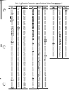
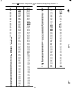
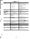
All thermistors are identical in their tem-
perature vs. resistance performance. Resistance at various
temperatures are listed in Tables 15 and 16.
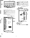
LOCATION
-
General location of thermistor sensors are
shown in Fig. 13.
Cooler Leaving Water Thermistor (Tl)
-
Tl is located in
leaving water nozzle. The probe is immersed directly in the
water. All thermistor connections are made through a
%-in.
coupling. See Fig. 15. Actual location is shown in Fig. 13
and 14.
Cooler Entering Water Thermistor (T2)
-
T2 is located in
cooler shell in first baffle space near tube bundle. Ther-
mistor connection is made through a
%-in.
coupling. See
Fig. 15. Actual location is shown in Fig. 13 and 14.
Compressor Suction Gas Temperature Thermistors
(T7
and
T8)
-
T7 and
T8
are located in lead compressor in each
circuit in suction passage between motor and cylinders, above
oil pump. They are well-type thermistors on 040-210 and
associated modular units, or ferrule-type on 225, 250, 280
units. See Fig. 13 and 14.
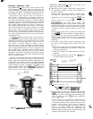
THERMISTOR REPLACEMENT (Tl , T2, T7, TS) (Com-
pressor and Cooler)
Thermistors are installed directly in fluid or refrigerant
circuit. Relieve all refrigerant pressure using standard
refrigerant practices or drain fluid before removing.
Proceed as follows (see Fig. 15):
To replace sensors
Tl,
T2, T7 (225,250,280), and
T8
(225,250,280)
1. Remove and discard original thermistor and coupling.
IMPORTANT: Do not disassemble new coupling.
Install as received.
I
2. Apply pipe sealant to
‘/a-in.
NPT threads on replace-
ment coupling and install in place of original. Do not
use packing nut to tighten coupling. This damages fer-
rules (see Fig. 15).
3. Insert new thermistor in coupling body to its full depth.
If thermistor bottoms out before full depth is reached,
pull thermistor back out
I/s
in, before tightening packing
nut. Hand tighten packing nut to position ferrules, then
finish tightening
19’4
turns with a suitable tool. Ferrules
are now attached to thermistor which can be withdrawn
from coupling for unit servicing.
To replace thermistors T7 and T8 (040-210 and associated
modular units):
Add a small amount of thermal conductive grease to ther-
mistor well. Thermistors are friction-fit thermistors, which
must be slipped into receiver located in the compressor pump
end.
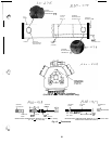
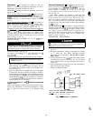
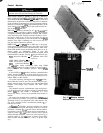
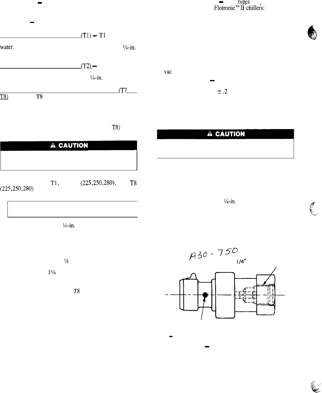
Pressure Transducers
-
TWO
tvpes
of pressure trans-
ducers are used on 30G Flotronic’”
Ii*chille&:
a low pres-
sure transducer and a high pressure transducer. The low
pressure transducer is identified by a white dot on the body
of the transducer, and the high pressure transducer by a red
dot. See Fig. 16.
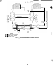
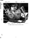
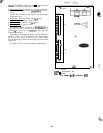
Three pressure transducers are mounted on each lead com-
pressor: 2 low-pressure transducers to monitor compressor
suction pressure and oil pressure, and a high-pressure trans-
ducer to monitor compressor discharge pressure (see
Fig. 17 for exact locations on compressor). Each transducer
is supplied with 5 vdc power from a rectifier which changes
24 vat to 5 vdc.
TROUBLESHOOTING
-
If transducer is suspected of be-
ing faulty, first check supply voltage to transducer. Supply
voltage should be 5 vdc + .2 v. If supply voltage is cor-
rect, compare pressure reading displayed on keypad and dis-
play module against pressure shown on a calibrated pres-
sure gage. If the 2 pressure readings are not reasonably close,
replace pressure transducer.
TRANSDUCER REPLACEMENT
Transducers are installed directly in the refrigerant cir-
r
cuit. Relieve all refrigerant pressure using standard re-
frigeration practices before removing.
1. Relieve refrigerant pressure using standard refrigeration
practices.
2. Disconnect transducer wiring at transducer by pulling
up on locking tab while pulling weather-tight connection
pfug from end of transducer. Do not pull on trans-
ducer wires.
3. Unscrew transducer from
!&in.
male flare fitting. When
installing new pressure transducer, do not use thread
sealer. Thread sealer can plug transducer and render it
inoperative.
4. Insert weathertight wiring plug into end of transducer
until locking tab snaps in place.
5. Check for refrigerant leaks.
-75”
l/4”
SAE FEMALE FLARE
WHITE DOT-LOW PRESSURE TRANSDUCER
RED DOT -HIGH PRESSURE TRANSDUCER
SAE
-
Society of Automotive Engineers
Fig. 16
-
Pressure Transducer
60