


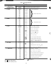
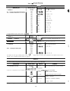

Example 2
-
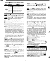
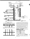
Reading Current Operating Modes
KEYPAD
I
DISPLAY
ENTRY RESPONSE
I
COMMENTS
TUE
15:45
Keypad has not been used for at
LOCAL ON
least 10 minutes Rotating summary
COOL 1
display appears on screen
0 ALARMS
p-lH
2 MODES
There are 2 modes currently in effect
cl
4
LOCAL ON
Unit is on by chiller on/off switch
cl
+
MODE 8
Temperature reset is in effect
l-ii
1;;;;1
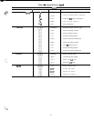
(Stage)
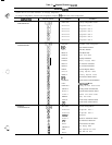
-
This subfunction displays the capac-
ity stage number. See Tables 4A-4D for compressor load-
ing sequence. To enter the STAGE subfunction, press
p--&q and use the q to display the stage number.
Additional
m
provides the following information:
Percent of total unit capacity being utilized.
Percent of each circuit capacity being utilized.
Demand limit set point in effect (can be any value be-
tween 0% and 100%).
Load limit set point in effect. This is a CCN function for
controlling operation of multiple units between 0% and
100% of total capacity of all units combined.
Status of each compressor relay. When a compressor is
on, the number of that compressor is displayed. If a com-
pressor is off, a 0 is displayed. For example: In a given
circuit, if compressors 1 and 3 are running, and 2 and 4
are not running, 0301 is displayed for that circuit.
Load/Unload factor for compressors. This factor is an in-
dication of when a step of capacity is added or sub-
tracted. Its value can range from slightly less than -1 .O
to slightly more than + 1 .O. When load/unload factor
reaches + 1.0, a compressor is added. When the load/
unload factor reaches -1 .O, a compressor is subtracted.
If compressor unloaders are used, at
-.6
a compressor is
unloaded and at + .6, a compressor is loaded up.
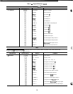
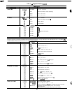
mF[
(Set Point)
-
This subfunction displays leaving
water temperature and leaving chilled water set point. If
unit is programmed for dual set point, the chilled water set
point currently in effect (either occupied or unoccupied) is
displayed. If reset is in effect, the unit operates to the mod-
ified chilled water set point. This means the leaving water
temperature may not equal the chilled water set point The
modified chilled water set point can also be displayed in the
Status function. To enter the set point subfunction, de-
press
mb[
and use the
q
to display modified leaving
chilled water set point followed by leaving water set point
and actual cooler leaving fluid temperature.
F[
F[
(Temperature)
-
The temperature subfunction dis-
plays the readings at temperature sensing thermistors.
To read a temperature, enter
Fi
Fi
, then scroll to de-
sired temperature using the
m
key. See Table 9 for the
order of readouts.
flH
(Pressure)
-
This subfunction displays suction,
discharge and net oil pressure at lead compressor of each
circuit of unit.
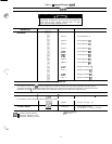
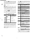
m
H
(Analog Inputs)
-
This subfunction displays
analog inputs, if any. Enter
m
Fi
, then use the
q
. The
transducer supply voltage, 4-20 mA reset signal can be dis-
played. This is useful for problem diagnosis prior to using
the test function.
m
bi
(Inputs)
-
This subfunction displays status
(ON/OFF) of input switch where applicable. Status of dual
set point switch, and demand limit switches 1 and 2 can be
displayed. This is useful for problem diagnosis prior to us-
ing the test function.
~~
(Outputs)
-
This function displays ON/OFF sta-
tus of alarm relay, all fan relays, and chilled water pump
relay. It also displays ON/OFF status of compressor unload-
ers (if used). The position of each EXV (in percent open)
can be displayed.
TEST FUNCTION
-
The test function operates the diag-
nostic program. To initiate test function, the LOCAL/
ENABLE-STOP-CCN switch must be in STOP position.
To reach a particular test, enter its subfunction number,
then scroll to desired test by pressing the
(
key. Press
B
to start a test. Press
q
or
q
or
H
to terminate or
exit a test. Pressing the
q
key after a test has started ad-
vances system to next test, whether current test is operating
or has timed out, Once in the next step, you may start
test by pressing
H
or advance past it by pressing
I)I
.
While the unit is in test, you may leave test function and
access another display or function by pressing appropriate
keys. However, a component that is operating when an-
other function is accessed remains operating. You must
re-enter test function and press the
)
key to shut down
the component. Components with a timed operating limit
time out normally even if another function is accessed.
Keypad entry
riF[
allows the operator to make the
following checks by using
m
:
LID display check. Propezisplay is 8.8.8.8.8.8.8.8 .
Operation of remote alarm.
Operation of condenser fans.
Operation of chilled water pump.
Operation of EXVs. To drive EXV fully open, enter
m
m
m
(100% open). To drive EXV fully closed,
en-
ter
u
(0% open).
c
Keypad entry
-mH
I
accesses the compressor and.
compressor unloader
operational
tests.
During compressor operational tests, compressor starts
and runs for 10 seconds. Compressor service valves must
be open. Energize crankcase heaters 24 hours prior to
performing compressor tests.
Since test function checks only certain outputs, it is good
practice to also check all inputs and outputs accessible
through the status function. These are located at
F\
F[
,
m
H,
and
mm
(see Table 9). If keypad is not used
for 10 minutes, unit automatically leaves test function and
resumes rotating display. See Example 3.
38