


_I.:
,/:.
::.
i
.‘I
Because the EXVs are controlled by the processor mod-
ule, it is possible to track valve position. During initial
start-up, EXV is fully closed. After start-up, valve po-
sition is tracked by processor by constantly observing
amount of valve movement.
The processor keeps track of EXV position by counting
the number of open and closed steps it has sent to each
valve. It has no direct physical feedback of valve posi-
tion. Whenever unit is switched from STOP to RUN po-
sition, both valves are initialized, allowing the proces-
sor to send enough closing pulses to the valve to move it
from fully open to fully closed, then reset the position
counter to zero.
4. The EXV test can be used to drive EXV to any desired
position. When EXV opens, the metering slots begin to
provide enough refrigerant for operation at these steps:
step 60 for sizes 040-210 and associated modular units,
or
145
for sizes 225, 250, and 280. This is fully closed
position when circuit is operating. The fully open posi-
tion is 760 steps.
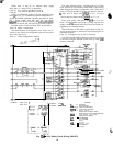
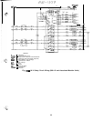
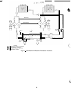
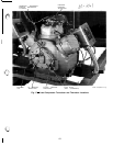
5. Check thermistors and pressure transducers that control
EXV. Check thermistors and pressure transducers that
control processor output voltage pulses to EXVs. See
Fig, 13 for locations.
Circuit A
-
Thermistor T7, Suction Pressure Trans-
ducer SPTA
Circuit B
-
Thermistor T8, Suction Pressure Trans-
ducer SPTB
a. Use temperature subfunction of the status function
(m
bi
)
to determine if thermistors are reading
correctly.
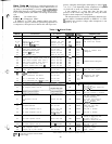
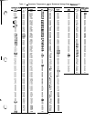
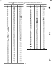
b. Check thermistor calibration at known temperature
by measuring actual resistance and comparing value
measured with values listed in Tables 15 and 16.
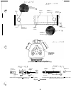
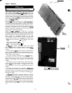
c. Make sure thermistor leads are connected to proper
pin terminals at
57
terminal strip on processor mod-
ule and that thermistor probes are located in proper
position in refrigerant circuit. See Fig. 14 and 15.
d. Use the pressure subfunction of the Status function
(
m
Fl)
to determine if pressure transducers are
reading correctly. Connect a calibrated gage to lead
compressor suction or discharge pressure connection
to check transducer reading.
e. Make sure transducer leads are properly connected in
junction box and at processor board. Check trans-
former 5 output. Check voltage transducer 5 vdc +
.2 v.
When above checks have been completed, check ac-
tual operation of EXV by using procedures outlined
in Step 5.
6. Check operation of EXV.
a. Close liauid line service valve of circuit to be checked,
and run ihrough the test step (
17
Fi
)
for lead com-
nressor
in that circuit to pump down low side of
sys-
iem. Repeat test step 3
tcmes-to
ensure all refrigerant
has been pumped from low side.
NOTE: Be sure to allow compressors to run for the
full
pumpout
period.
b. Turn off compressor circuit breaker(s). Close com-
pressor discharge service valves and remove any re-
maining refrigerant from low side of system.
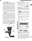
c. Remove screws holding top cover of EXV. Carefully
remove top cover. If EXV plug was disconnected dur-
ing this process, reconnect it after cover is removed.
When removing top cover, be careful to avoid dam-
aging motor leads.
d. Enter appropriate EXV test step for EXVA or
EXVB in the outputs subfunction of the test function
(jlF[).
Press-mmriH
to initiate test. With
cover lifted off EXV valve body, observe operation
of valve motor and lead screw. The motor should
turn counterclockwise, and the lead screw should move
up out of motor hub until valve is fully open. Lead
screw movement should be smooth and uniform from
fully closed to fully open position. Press
l-+$0
check open to closed operation.
If valve is properly connected to processor and re-
ceiving correct signals, yet does not operate as de-
scribed above, valve should be replaced.
Operation of EXV valve can also be checked without
removing top cover. This method depends on oper-
ator’s skill in determining whether or not valve is
moving. To use this method, initiate EXV test and
open valve. Immediately grasp EXV valve body. As
valve drives open, a soft, smooth pulse is felt for ap-
proximately 26 seconds as valve travels from fully
closed to fully open. When valve reaches end of its
opening stroke, a hard pulse is felt momentarily. Drive
valve closed and a soft, smooth pulse is felt for the
26 seconds necessary for valve to travel from fully
open to fully closed. When valve reaches end of its
stroke, a hard pulse is again felt as valve overdrives
by 50 steps. Valve should be driven through at least
2 complete cycles to be sure it is operating properly.
If a hard pulse is felt for the 26 second duration, valve
is not moving and should be replaced.
The EXV test can be repeated as required by enter-
ing any percentage from 0 (
r;l
)
to 100 to initiate
movement.
If operating problems persist after reassembly, they
may be due to out-of-calibration thermistor(s) or inter-
mittent connections between processor board terminals
and EXV plug. Recheck all wiring connections and volt-
age
signals,
Other possible causes of improper refrigerant flow con-
trol could be restrictions in liquid line, Check for plugged
filter drier(s) or restricted metering slots in the EXV.
Formation of ice or frost on lower body of electronic ex-
pansion valve is one symptom of restricted metering slots.
However, frost or ice formation is normally expected
when leaving fluid temperature from the cooler is below
40 F. Clean or replace valve if necessary.
NOTE: Frosting of valve is normal during compressor
Test steps and at initial start-up. Frost should dissipate
after 5 to 10 minutes operation in a system that is oper-
ating properly. If valve is to be replaced, wrap valve
with a wet cloth to prevent excessive heat from damag-
ing internal components.
57