


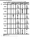
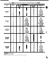
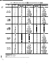
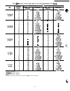
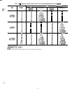
OPERATION DATA
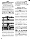
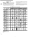
Capacity Control
-
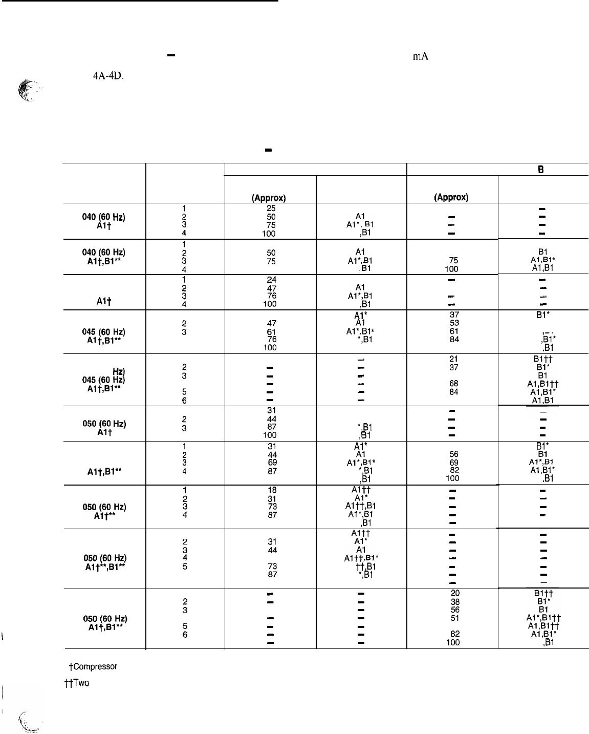
The control system cycles
compressor to give capacity control steps as shown in
Tables 4A-4D. The unit controls leaving chilled water tem-
perature. Entering water temperature is used by the micro-
processor in determining the optimum time to add or sub-
tract steps of capacity, but is not a control set point.
The chilled water temperature set point can be automat-
ically reset by the return temperature reset or space and out-
door air temperature reset features. It can also be reset from
an external 4-20 mA signal with a loop isolator, or from a
network signal.
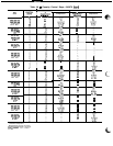
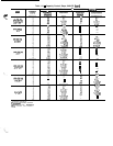
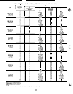
The operating sequences shown are some of many pos-
sible loading sequences for the control of the leaving water
temperature. If a circuit has more unloaders than another,
that circuit will always be the lead circuit.
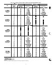
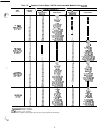
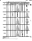
Table
4A
-
Capacity Control Steps, 040-070
Compressors
-
-
-
-
LOADING SEQUENCE
B
%
Displacement
tAppro
-
-
-
25
50
1::
-
-
-
:;
Bl*
AIBlil
*
Al’,Bl
-
-
-
-
,
4
Al ‘,Bl
El
5
1::
Al ,Bl
100
1
- -
- -
040 (50 Hz)
o;y;,y
:
::
-
-
53
4
-
-
,
i
- -
i:
- -
100
045 (50 Hz)
1
050f”,
Hz)
;
i:
Al*
-
Al
-
1::
Al *,Bl
-
4
Al ,Bl
-
Bl*
Al& *
Al ,‘sl*
Al
.Bl
UNIT
30GN
“““ft
Hr)
y-yy
,
040 (60 Hz)
045 (60 Hz)
AIt
040 (50 Hz)
0:;
pg~l
CONTROL
STEPS
:
i
:
i
:
:
1
:
LOADING SEQUENCE A
%
Displacement Compressors
(AwrW
Al*
::
1~~
APB1
Al
:Bl
25
Al*
%
Al”B1
100
Al
,kl
s;
Al”
1;:
Al”B1
Al
,k
24
Al*
::
Al%
*
-
-
-
045 (50 Hz)
:
:A
Al*
38
050 (60 Hz)
:
8°F
Al%
*
Al ‘,Bl
::
Alt,Bl**
5
100
Al
,Bl
1%
045 (50 Hz)
: ;:
A2-y
-
-
050A\6$Hz)
:
is;
y&tgi
-
-
5 100
Al
,i31
-
1
18
-
045 (50 Hz)
:
::
A2.p
-
-
yfyy2
z
56
Al;Bl*
-
I
2
Al
+,Bl
-
6
Al *,Bl
-
7 100
Al ,Bl
-
1
-
-
045 (50 Hz)
32
- -
El
-
4
- -
z7
i
-
-
64
- -
7
- -
1::
Bl”
Al%
*
Al,k
Al
.Bl
-
-
-
-
-
-
-
-
-
-
Al
,Bl
*Unloaded compressor.
tCompressor unloader, standard.
**Compressor unloader, accessory.
ttTwo
unloaders, both unloaded.
5