


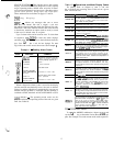
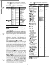
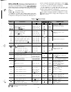
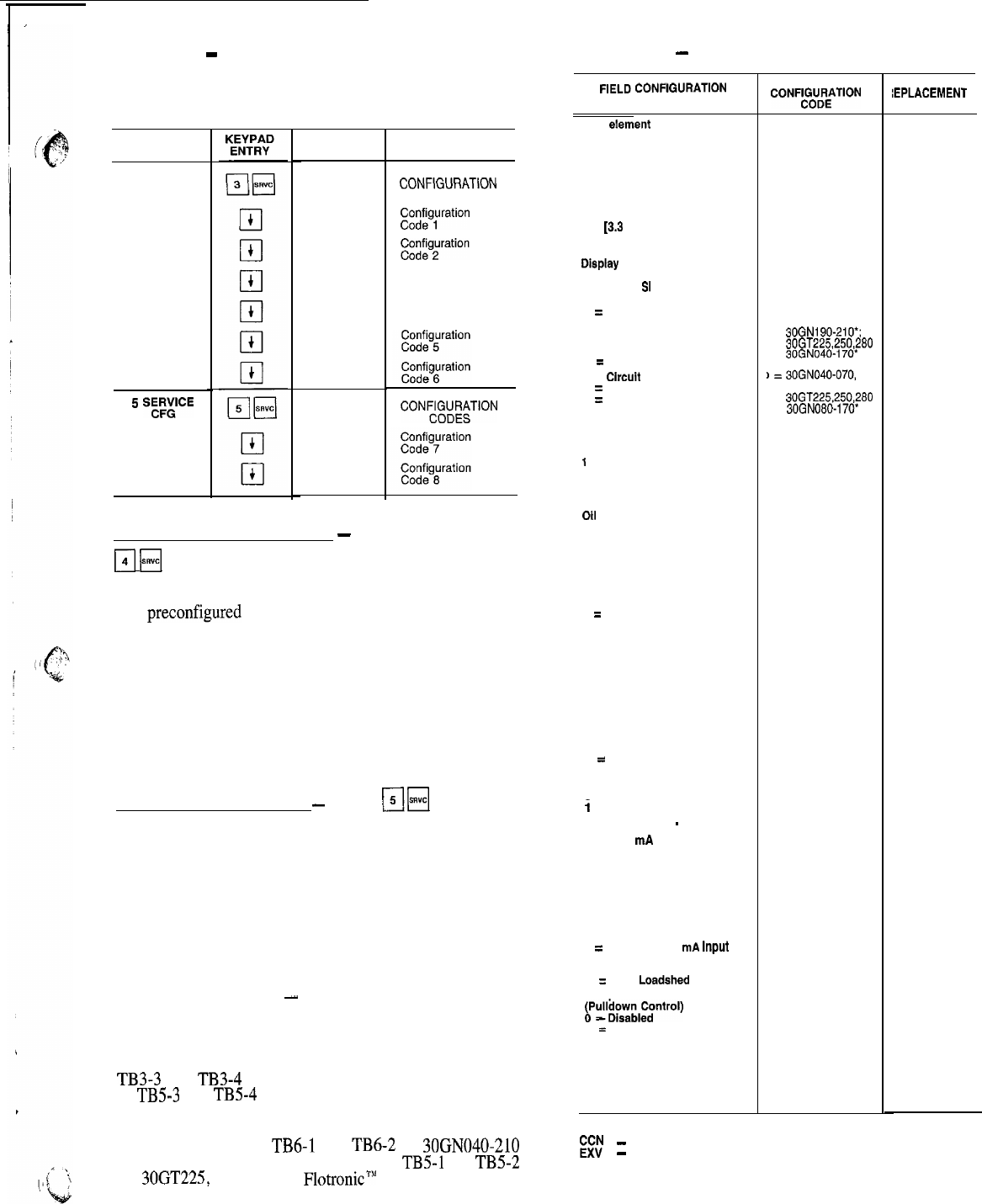
Table 12
-
Factory Configuration Keystrokes
To change a configuration enter the new configuration
and press
q
while on the correct configuration.
SUB-
FUNCTION
3 FACTORY
CFG
5
%FE
DISPLAY COMMENTS
FACT CFG
xxxxxxxx
xxxxxxxx
xxxxxxxx
xxxxxxxx
xxxxxxxx
xxxxxxxx
FACTORY
CONFlGURATlON
CODES
CJz;;g;ration
Configuration
Code 3
Configuration
Code 4
SRV CFG
SERVICE
CONW;;T’ON
xxxxxxxx
xxxxxxxx
Adiustable Field Configurations
-
After logging on, press
ri
H
to enter subfunction. The subfunction allows oper-
ation of the chiller to be customized to meet the particular
needs of the application. The chiller comes from the fac-
tory
preconfigured
to meet the needs of most applications.
Each item should be checked to determine which configu-
ration alternative best meets the needs of a particular appli-
cation. See Table 13 for factory loaded configuration codes
and alternative configurations.
If processor module is replaced, the replacement module
is preloaded with factory default configuration codes. Each
configuration code must be checked and, if necessary, re-
configured to meet needs of the application. See
Table 13 for pre-loaded service replacement configuration
codes.
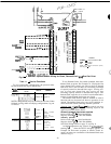
Service Configuration Codes
-
Press
r;lH
to enter the
service configuration subfunction. The first 2 items under
this subfunction are 2 groups (8 digits each) of configura-
tion codes that are downloaded at the factory. If processor
module is replaced in the field, the 2 groups of configura-
tion codes must be entered through the keypad and display
module. The 2 groups of configuration codes (groups 7 and
8) that apply to the unit being serviced can be found on a
label diagram inside the control box cover. See Table 12
for keystroke information to enter configuration codes 7
and 8.
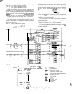
SCHEDULE FUNCTION
-
This function provides a means
to automatically switch chiller from an occupied mode to
an unoccupied mode, When using schedule function, chilled
water pump relay must be used to switch chilled water pump
on and off. Connections for chilled water pump relay are:
TB3-3 and TB3-4 (040-210 and associated modular units)
or TB5-3 and TB5-4 (225, 250, and 280 units). The chilled
water pump relay starts chilled water pump but compres-
sors do not run until remote chilled water pump interlock
contacts are between TB6-1 and TB4-2 on 30GN040-210
and associated modular units, or between TB5-1 and TB5-2
on 3OGT225, 250, and 280 Flotronic” units are closed and
leaving chilled water temperature is above set point. If a
remote chilled water pump interlock is not used, the first
compressor starts (upon a call for cooling) approximately
one minute after chilled water pump is turned on.
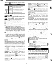
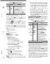
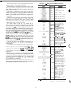
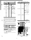
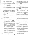
Table 13
-
Adjustable Field Configurations
FIELD
CONFlGURATlON
ITEM AND CODES
CCN element address
(Entered by CCN Technician)
CCN Bus Number
(Entered by CCN Technician)
CCN Baud Rate
(Entered by CCN Technician)
Cooler Fluid Select
1 = Water (38 to 70 F
[3.3 to 21 C] Set Point)
2 = Medium Brine (15 to 70 F
f-9 to 21 C] Set Point)
Display Unit Select
0 = English
1 = Metric
SI
Display Language Select
1
=
English
No. Circuit A Unloaders
0 = No Unloaders
1 = One Unloader
2
=
Two Unloaders
No. Circuit B Unloaders
0
=
No Unloaders
1
=
One Unloader
2 = Two Unloaders
Hot Gas Bypass Select
0 = No Valve
Loading Sequence Select
1
= Equal Circuit Loading
2 = Staged Circuit Loading
Lead/Lag Sequence Select
1 = Automatic
Oil Pressure Switch Select
0 = Not Used
1 = Air Cooled
Head Pressure Control Type
0 = Not Used
1 = Air Cooled
Head Pressure Control Method
1 = EXV Controlled
2
=
Set Point Control for
Both Circuits
3 = Set Point Control for
Circuit A; EXV Control
for Circuit B
4 = Set Point Control for
Circuit B; EXV Control
for Circuit A
Cooling Set Point
Control Select
0 = Single Set Point Control
1 = External Switch
Controlled Set Point
2
=
Clock Controlled
Set Point
Cooling Reset
0 = No Reset
Control
Select
i
= Return Fluid Reset
2 = External Temperature
Reset
-
3 = 4-20 mA Controlled
Reset
External Reset Sensor Select
0 = Thermistor Connected to
Options Module
1 = Obtained Through CCN
Demand Limit Control Select
0 = No Demand Limiting
1 = Two External Switch Input
2 = External 4-20
mA
Input
3 = CCN Load Limiting
(Multi-Unit)
4
=
CCN Loadshed Interface
Ramo Load Select
~P@os~dol~ntrol)
1
=
Enabled
Cooler Pump Interlock Select
0 = No Interlock
1 = With Interlock
Cooler Pump Control Select
0 = Not Controlled
1 = ON/OFF Controlled
FACTORY
CONFF$ikTlON
001 001
000 000
9600
9600
= Standard Models
1
0
1
0
0
0
1
1
0
0
1
0
0
0
0
0
0
0
I = Brine Models
0
I =
30GN190-HO*;
30GT225,250,280
=
30GN040-170*
)
=
30GN040-070,
190-210';
30GT225,250,280
=
30GN080-170*
0
0
0
0
0
0
LEGEND
EE
-
Carrier Comfort Network
-
Electronic Expansion Valve
*And associated modular units
SERVICE
IEPLACEMENT
CODE
45