


1.
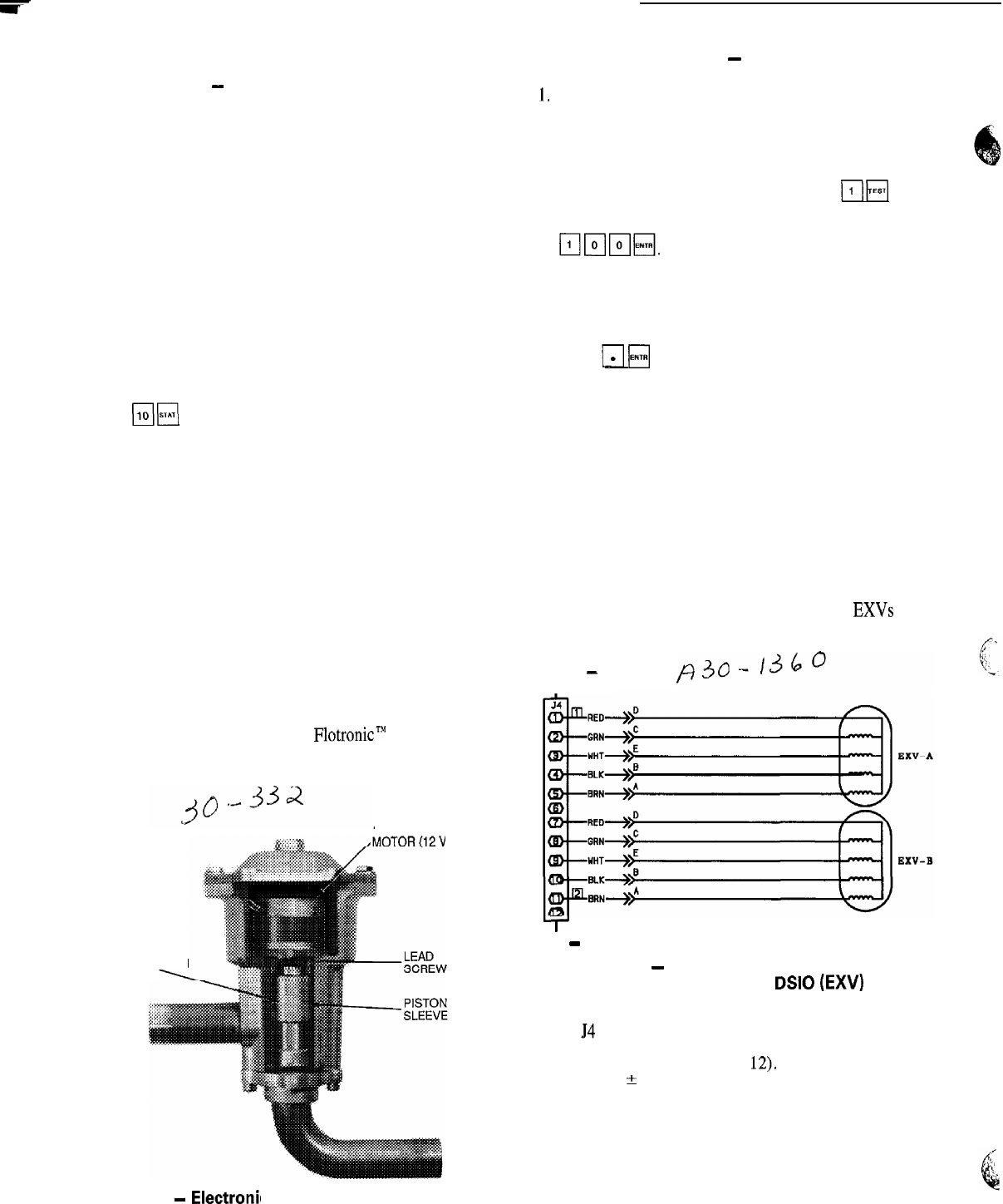
Electronic Expansion Valve
EXV OPERATION
-
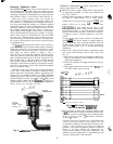
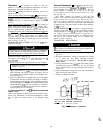
These valves control the flow of liq-
uid refrigerant into the cooler. They are operated by pro-
cessor to maintain a specified superheat at lead compressor
entering gas thermistor (located between compressor motor
and cylinders). There is one EXV per circuit. See Fig. 11.
High-pressure liquid refrigerant enters valve through bot-
tom. A series of calibrated slots are located in side of ori-
fice assembly. As refrigerant passes through orifice, pres-
sure drops and refrigerant changes to a 2-phase condition
(liquid and vapor). To control refrigerant flow for different
operating conditions, sleeve moves up and down over ori-
fice, thereby changing orifice size. Sleeve is moved by a
linear stepper motor. Stepper motor moves in increments
and is controlled directly by processor module. As stepper
motor rotates, motion is transferred into linear movement
by lead screw. Through stepper motor and lead screws,
760 discrete steps of motion are obtained. The large num-
ber of steps and long stroke result in very accurate control
of refrigerant flow.
The
biF\
subfunction shows EXV valve position as
a percent of full open. Position should change constantly
while unit operates. If a valve stops moving for any reason
(mechanical or electrical) other than a processor or ther-
mistor failure, the processor continues to attempt to open or
close the valve to correct the superheat. Once the calcu-
lated valve position reaches 60 (fully closed) for 040-210
and associated modular units, 145 (fully closed) for 225,
250, and 280 units, or 760 (fully open) it remains there. If
EXV position reading remains at 60, 145 or 760, and the
thermistors and pressure transducers are reading correctly,
the EXV is not moving. Follow EXV checkout procedure
below to determine cause.
The EXV is also used to limit cooler suction temperature
to 50 F (10 C). This makes it possible for chiller to start at
higher cooler water temperatures without overloading com-
pressor. This is commonly referred to as MOP (maximum
operating pressure), and serves as a load limiting device to
prevent compressor motor overloading, This MOP or load
limiting feature enables the 30G
FlotronicT’
II chillers to
operate with up to 95 F (35 C) entering water temperatures
during start-up and subsequent pull-down.
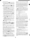
ORIFICE
ASSEMBLY
(INSIDE PISTON
SLEEVE)
Fig. 11
-
Electronil c Expansion Valve (EXV)
STEPPER
‘DC)
CHECKOUT PROCEDURE
-
Follow steps below to di-
agnose and correct EXV problems.
1,
Check EXV driver outputs. Check EXV output signals
at appropriate terminals on EXV driver module (see
Fig. 12) as follows:
Connect positive test lead to terminal 1 on EXV driver.
Set meter for approximately 20 vdc. Enter outputs
subfunction of test function by pressing
riF[
, then
advance to EXVA test by pressing
q
8 times. Press
T;ip--p-&q*
The driver should drive the circuit A EXV
fully open. During next several seconds connect nega-
tive test lead to pins 2, 3, 4 and 5 in succession. Voltage
should rise and fall at each pin. If it remains constant at
a voltage or at zero v, remove connector to valve and
recheck.
Press
m
H
to close circuit A EXV. If a problem still
exists, replace EXV driver module. If voltage reading is
correct, expansion valve should be checked. Next, test
EXVB. Connect positive test lead to pin 7 and the neg-
ative test lead to pin 8, 9, 10, 11 in succession during
EXVB test.
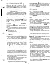
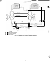
2. Check EXV wiring, Check wiring to electronic expan-
sion valves from terminal strip on EXV driver. See
Fig. 12.
a. Check color coding and wire connections. Make sure
they are connected to correct terminals at driver and
EXV plug connections.
b. Check for continuity and tight connection at all pin
terminals.
c. Check plug connections at driver and at EXVs to be
sure EXV cables are not crossed.
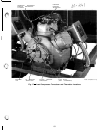
EXV DRIVER
BOARD
-
J4
I
T
EXV
-
Electronic Expansion Valve
Fig. 12
-
EXV Cable Connections to
EXV Driver Module,
DSIO
(EXV)
3. Check resistance of EXV motor windings. Remove plug
at
54
terminal strip and check resistance between com-
mon lead (red wire, terminal D) and remaining leads,
A, B , C, and E (see Fig. 12). Resistance should be
25 ohms
-1-
2 ohms.
Control of valve is by microprocessor. A thermistor and
a pressure transducer located in lead compressor are used
to determine superheat. The thermistor measures tem-
perature of the superheated gas entering the compressor
cylinders. The pressure transducer measures refrigerant
pressure in the suction manifold. The microprocessor con-
verts pressure reading to a saturation temperature. The
difference between temperature of superheated gas and
saturation temperature is the superheat.
56