


Liquid Propane
Units are shipped for use with natural gas, but may be field-
converted for use with liquid propane with accessory LP (liq-
uid propane) kit.
All LP gas equipment must conform to NFPA safety
standards.
LP gas pressure at the unit must not be less than 5 in. wg or
greater than 13 in. wg under full load. Maintaining proper
gas pressure depends on:
1. Vaporization rate. (Vaporization rate is determined by
the temperature of the LP and the level of LP in the
tank.)
2. Proper pressure regulation. (Two-stage regulation is more
cost effective and efficient.)
3. Pressure drop in lines between regulators and between
the second-stage regulator and the appliance. Pipe size
is determined by the length of the pipe run and the to-
tal load of all appliances.
Contact your LP gas supplier or regulator manufacturer for
further details regarding tank sizing, recommended regula-
tor settings, and pipe sizing.
Special pipe compound must be used when assembling pip-
ing for liquid propane gas as white lead or commercial com-
pounds will be easily dissolved. Use a shellac-based compound
suitable for use with LP.
D. Field Duct Connections
NOTE: The design and installation of the duct system must
be in accordance with the standards of the NFPA for the in-
stallation of nonresidence-type air-conditioning and ventilat-
ing systems, NFPA No. 90A or residence-type, NFPA No. 90B;
and/or local codes and ordinances.
Adhere to the following criteria when selecting, sizing, and
installing the duct system:
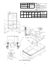
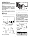
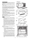
1. Remove appropriate panels from unit to obtain either a
horizontal or vertical application. If units are installed
for horizontal applications, remove vertical duct covers,
save screws, and install covers on vertical duct
openings.
2. Select and size ductwork, supply-air registers, and return-
air grilles according to ASHRAE (American Society of
Heating, Refrigeration and Air Conditioning Engi-
neers) recommendations.
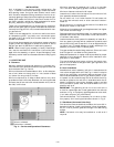
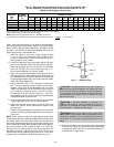
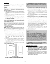
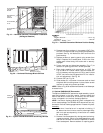
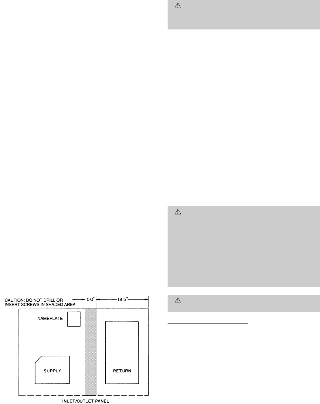
CAUTION:
When the duct system fastening holes are
being drilled into the side of the unit for duct flanges,
be careful not to puncture the coil or coil tubes. See
Fig. 12.
3. Use flexible transition between rigid ductwork and unit
to prevent transmission of vibration. The transition may
be screwed or bolted to duct flanges. Use suitable gas-
kets to ensure weather- and airtight seal.
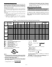
4. When horizontal return is used, install external, field-
supplied air filters in return-air ductwork where they
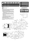
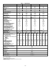
are easily accessible for service. Recommended filter sizes
are shown in Table 1.
5. For horizontal applications, be sure ductwork does not
cover nameplate.
6. Size all ductwork for maximum required airflow (either
heating or cooling) for unit being installed. Avoid abrupt
duct size increases or decreases.
7. Adequately insulate and weatherproof all ductwork lo-
cated outdoors. Insulate ducts passing through uncon-
ditioned space, and use vapor barrier in accordance with
latest issue of SMACNA (Sheet Metal and Air Condi-
tioning Contractors National Association) and ACCA(Air
Conditioning Contractors of America) minimum instal-
lation standards for heating and air-conditioning sys-
tems. Secure all ducts to building structure.
8. Flash, weatherproof, and vibration isolate all openings
in building structure in accordance with local codes and
good building practices.
E. Electrical Connections
WARNING:
The unit cabinet must have an uninter-
rupted, unbroken electrical ground to minimize the pos-
sibility of personal injury if an electrical fault should
occur. This ground may consist of electrical wire con-
nected to the unit ground lug in the control compart-
ment or conduit approved for electrical ground when
installed in accordance with the NEC (National Elec-
trical Code); ANSI/NFPA, latest edition, (in Canada,
Canadian Electrical Code CSA[Canadian Standards As-
sociation] C22.1); and local electrical codes. Do not use
gas piping as an electrical ground. Failure to adhere to
this warning could result in personal injury.
CAUTION:
Failure to follow these precautions could
result in damage to the unit being installed:
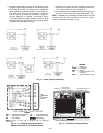
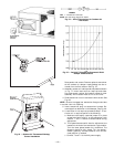
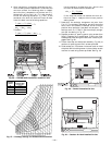
Field Power Supply (Fig. 13-15)
1. Make all electrical connections in accordance with NEC
ANSI/NFPA, latest edition, and local electrical codes gov-
erning such wiring. In Canada, all electrical connec-
tions must be in accordance with CSA standard C22.1
Canadian Electrical Code Part 1 and applicable local codes.
Refer to unit wiring diagram.
2. Use only copper conductor for connections between field-
supplied electrical disconnect switch and unit. DO NOT
USE ALUMINUM WIRE. Maximum wire size is no. 2
AWG (American Wire Gage).
Fig. 12 — Location of Coil Area Not To Be Drilled
—9—