


IV. FIELD CONNECTIONS
A. External Trap Condensate Drain
The unit’s
3
⁄
4
-in. condensate drain connections are located
at the bottom and side of the unit. Unit discharge connec-
tions do not determine the use of drain connections; either
drain connection can be used with vertical or horizontal
applications.
When using the standard side drain connection, make sure
the plug in the alternate bottom connection is tight before
installing the unit.
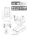
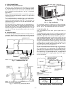
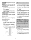
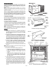
To use the bottom drain connection for a roof curb installa-
tion, relocate the factory-installed plug from the bottom con-
nection to the side connection. See Fig. 7. The piping for the
condensate drain and external trap can be completed after
the unit is in place.
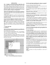
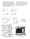
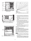
All units must have an external trap for condensate drain-
age. Install a trap at least 4-in. deep and protect against freeze-
up. See Fig. 8. If drain line is installed downstream from the
external trap, pitch the line away from the unit at 1 in. per
10 ft of run. Do not use a pipe size smaller than the unit
connection.
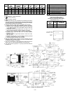
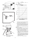
B. Install Flue Hood
Flue hood is shipped screwed to the burner compartment ac-
cess panel. Remove from shipping location and using screws
provided, install flue hood in location shown in Fig. 2 and 9.
For units being installed in California Air Quality Manage-
ment Districts which require NO
x
emissions of 40 nanograms/
joule or less, kit CRLOWNOX001A00 must be installed.
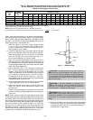
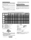
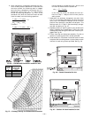
C. Gas Piping (Fig. 10)
Unit is equipped for use with type of gas shown on
nameplate.
The gas supply pipe enters the unit through the access hole
provided. The gas connection to the unit is made to the
1
⁄
2
-in.
female NPT gas inlet on the manual shutoff or gas valve.
Install a separate gas supply line that runs directly from the
meter to the heating section. Refer to Table 2 and the NFGC
for gas pipe sizing. Do not use cast iron pipe. Check the local
utility for recommendations concerning existing lines. Choose
a supply pipe that is large enough to keep the pressure loss
as low as practical. Never use pipe smaller than the
1
⁄
2
-in. fe-
male NPT gas inlet on the unit gas valve.
For natural gas applications, the gas pressure at unit gas con-
nection must not be less than 4 in. wg or greater than
13 in. wg while the unit is operating. On 581B048,060,072
high heat units, the gas pressure at unit gas connection must
not be less than 5 in. wg or greater than 13 in. wg while the
unit is operating. For propane applications, the gas pressure
must not be less than 5 in. wg or greater than 13 in. wg at
the unit connection.
NOTE: Drain plug is shown in factory-installed position.
Fig. 7 — Condensate Drain Pan
NOTE: Trap should be deep enough to offset maximum unit static dif-
ference. A 4-in. trap is recommended.
Fig. 8 — External Trap Condensate Drain
Fig. 9 — Flue Hood Details
LEGEND
NFGC — National Fuel Gas Code
*Field Supplied.
NOTE: Follow all local codes.
STEEL PIPE NOMINAL SPACING OF SUPPORTS
DIAMETER (in.) X DIMENSION (ft)
1
⁄
2
6
3
⁄
4
or 1 8
1
1
⁄
4
or Larger 10
Fig. 10 — Gas Piping Guide
(With Accessory Utility Connections Package)
—7—