


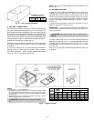
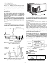
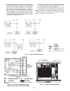
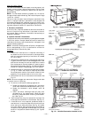
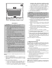
High-Voltage Connections (Fig. 13)
The unit must have a separate electrical service with a field-
supplied, waterproof, fused disconnect switch mounted at, or
within sight from the unit. Refer to the unit rating plate for
maximum fuse/circuit breaker size and minimum circuit amps
(ampacity) for wire sizing.
The field-supplied disconnect switch box may be mounted on
the unit over the high-voltage inlet hole in the control corner
panel.
Proceed as follows to complete the high-voltage connections
to the unit:
1. Connect ground lead to chassis ground connection when
using separate ground wire.
2. Pigtails are provided for field power connection.
Use factory-supplied splices or UL (Underwriters’
Laboratories) approved copper connector. Install con-
duit connectors in side panel power supply knockout
openings indicated in Fig. 2. Route power lines through
connector to unit control box.
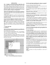
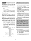
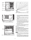
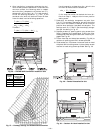
Special Procedures for 208-V Operation
DANGER: Make sure that the power supply to the
unit is switched OFF before making any wiring changes.
Electrical shock can cause personal injury or death.
For operation on 208 v, disconnect the black wire from the
230-v orange wire on the transformer and connect it to the
200-v red wire from the transformer. Insulate the end of the
orange wire.
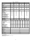
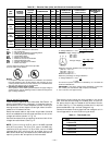
Table 3A — Electrical Data (Units Without Electrical Convenience Outlet)
UNIT
581B
NOMINAL
VOLTAGE
(V-Ph-Hz)
VOLTAGE
RANGE
COMPRESSOR OFM IFM
COMBUSTION
FAN MOTOR
POWER SUPPLY
MINIMUM UNIT
DISCONNECT
SIZE*
Min Max RLA LRA FLA FLA FLA MCA MOCP† FLA LRA
036
(3 Tons)
208/230-1-60 187 254 16.0 88.0 0.7 4.9 .57 25.6/25.6 35/35 25/25 101/101
208/230-3-60 187 254 10.3 77.0 0.7 4.9 .57 18.5/18.5 25/25 18/18 90/ 90
460-3-60 414 508 5.1 39.0 0.4 2.2 .30 9.0 15 9 46
575-3-60 518 632 4.2 31.0 0.4 2.2 .30 7.3 15 7 37
048
(4 Tons)
208/230-1-60 187 254 23.7 129.0 0.7 4.9 .57 35.2/35.2 45/45 34/34 142/142
208/230-3-60 187 254 13.5 99.0 0.7 4.9 .57 22.5/22.5 30/30 22/22 112/112
460-3-60 414 508 7.4 49.5 0.4 2.2 .30 9.7 15 12 57
575-3-60 518 632 5.8 40.0 0.4 2.2 .30 9.3 15 9 46
060
(5 Tons)
208/230-1-60 187 254 28.8 169.0 1.5 8.8 .57 46.3/46.3 60/60 45/45 216/216
208/230-3-60 187 254 17.3 123.0 1.5 5.8 .57 29.0/29.0 35/35 28/28 168/168
460-3-60 414 508 9.0 62.0 0.8 2.6 .30 14.7 20 14 84
575-3-60 518 632 7.1 50.0 0.8 2.6 .30 11.6 15 11 59
072
(6 Tons)
208/230-3-60 187 254 20.5 156.0 1.4 5.8 .57 32.8/32.8 40/40 32/32 200/200
460-3-60 414 508 9.6 70.0 0.6 2.6 .30 15.2 20 15 92
575-3-60 518 632 7.7 56.0 0.6 2.6 .30 12.2 15 12 74
LEGEND
FLA — Full Load Amps
HACR — Heating, Air Conditioning and Refrigeration
IFM — Indoor (Evaporator) Fan Motor
LRA — Locked Rotor Amps
MCA — Minimum Circuit Amps
MOCP — Maximum Overcurrent Protection
NEC — National Electrical Code
OFM — Outdoor (Condenser) Fan Motor
RLA — Rated Load Amps
UL — Underwriters’ Laboratories
*Used to determine minimum disconnect per NEC.
†Fuse or HACR circuit breaker.
NOTES:
1. In compliance with NEC requirements for multimotor and combina-
tion load equipment (refer to NEC Articles 430 and 440), the over-
current protective device for the unit shall be fuse or HACR breaker.
The CUL units may be fuse or circuit breaker.
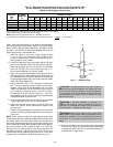
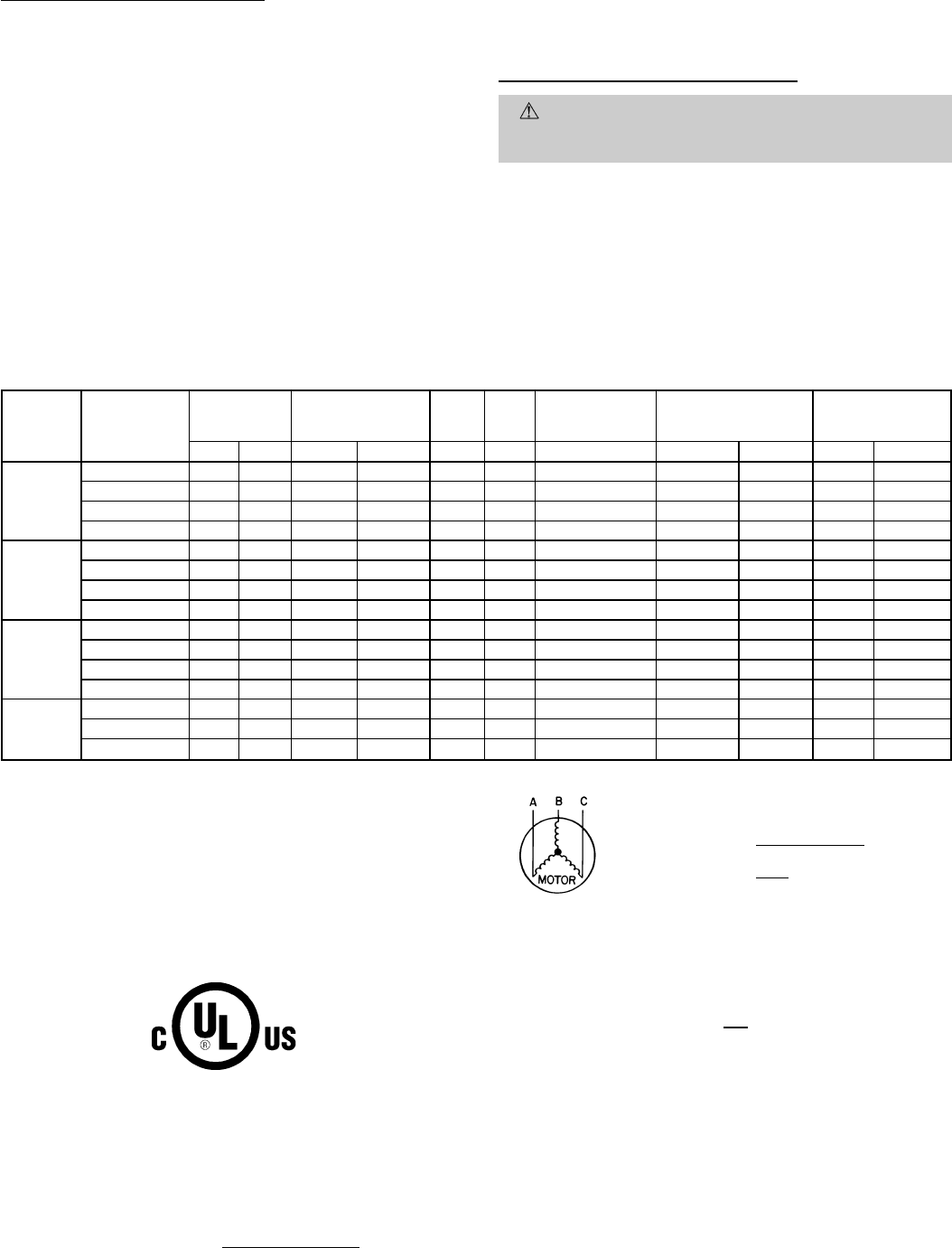
2. Unbalanced 3-Phase Supply Voltage
Never operate a motor where a phase imbalance in supply voltage is
greater than 2%.
Use the following formula to determine the percent-
age of voltage imbalance.
max voltage deviation
from average voltage
% Voltage Imbalance = 100 x
average voltage
EXAMPLE: Supply voltage is 460-3-60.
AB = 452 v
BC = 464 v
AC = 455 v
452 + 464 + 455
Average Voltage =
3
1371
=
3
= 457
Determine maximum deviation from average voltage.
(AB) 457 – 452=5v
(BC) 464 – 457=7v
(AC) 457 – 455=2v
Maximum deviation is 7 v.
Determine percentage of voltage imbalance:
7
% Voltage Imbalance = 100 x
457
= 1.53%
This amount of phase imbalance is satisfactory as it is below the
maximum allowable 2%.
IMPORTANT: If the supply voltage phase imbalance is more than
2%, contact your local electric utility company immediately.
3. 575-v units are UL, Canada approved only.
—11—