


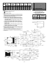
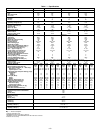
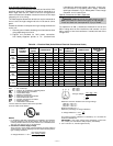
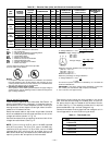
3. Voltage to compressor terminals during operation must
be within voltage range indicated on unit nameplate (also
see Tables 3A and 3B). On 3-phase units, voltages be-
tween phases must be balanced within 2% and the cur-
rent within 10%. Use the formula shown in Tables 3A
and 3B, Note 2, to determine the percent voltage im-
balance. Operation on improper line voltage or exces-
sive phase imbalance constitutes abuse and may cause
damage to electrical components. Such operation would
invalidate any applicable warranty.
4. Insulate low-voltage wires for highest voltage con-
tained within conduit when low-voltage control wires are
run in same conduit as high-voltage wires.
5. Do not damage internal components when drilling through
any panel to mount electrical hardware, conduit, etc.
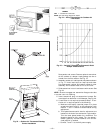
NOTE: If accessory thru-the-bottom connections and roof curbs
are used, refer the Thru-the-Bottom Installation Instruc-
tions for information on power wiring.
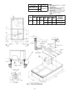
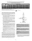
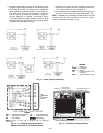
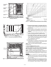
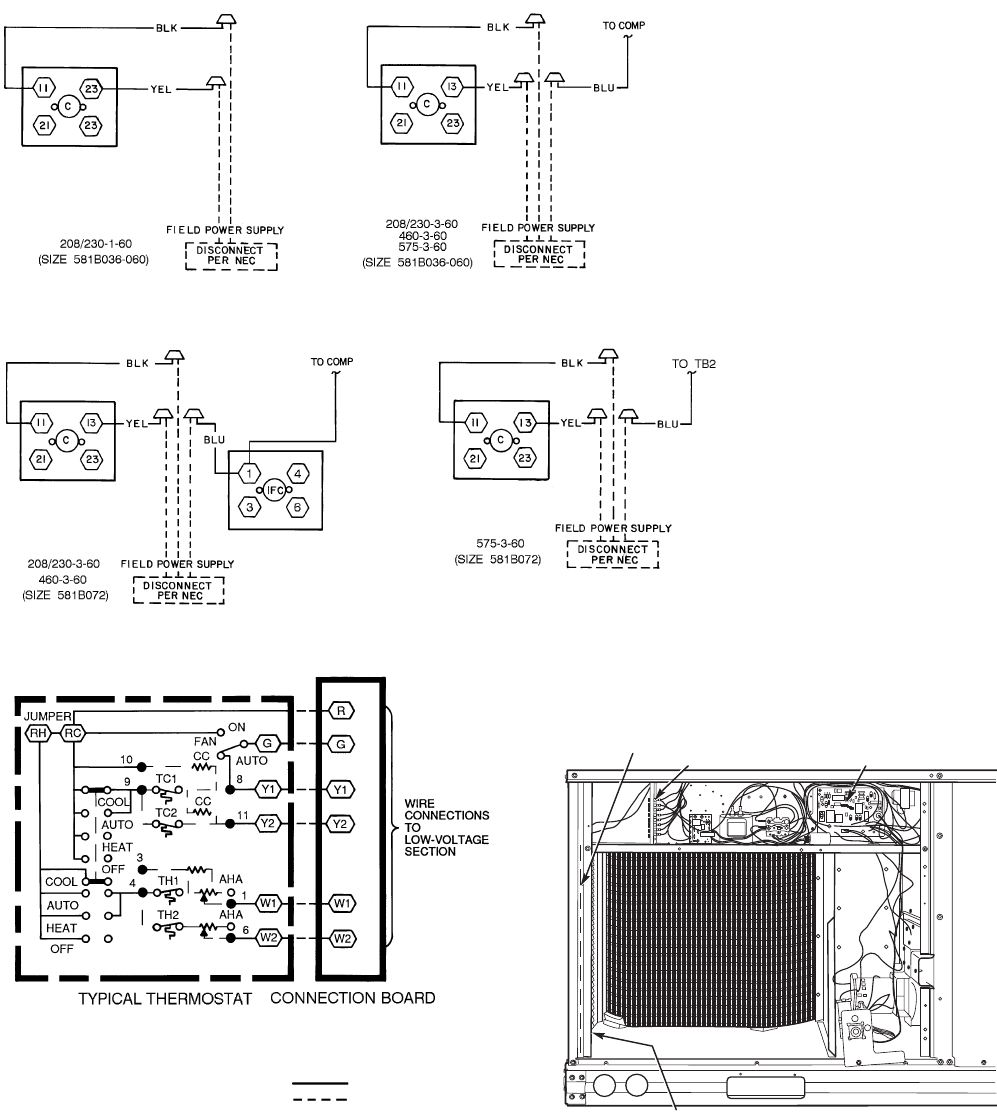
Fig. 13 — Power Wiring Connections
LEGEND
AHA — Adjustable Heat Anticipator TC — Thermostat-Cooling
CC — Cooling Compensator TH — Thermostat-Heating
RC — 24-v Cooling
Field Wiring
RH — 24-v Heating
Factory Wiring
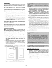
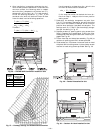
NOTE: Connect Y2 when unit is equipped with an integrated
economizer.
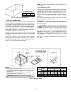
Fig. 14 — Low-Voltage Connections With or
Without Economizer or Two-Position Damper
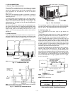
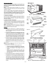
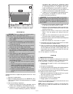
LOW VOLTAGE
CONNECTIONS
(SCREW TERMINALS)
INTEGRATED GAS UNIT
CONTROLLER (IGC)
HOLE IN END PANEL (HIDDEN)
RACEWAY
Fig. 15 — Field-Control Wiring Raceway
LEGEND
C—Contactor
COMP — Compressor
EQUIP — Equipment
GND — Ground
IFC — Indoor (Evaporator) Fan
Contactor
NEC — National Electrical Code
—10—