


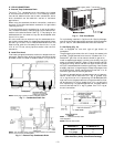
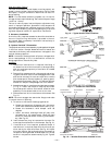

Save panels and screws. Remove optional economizer
so the outdoor-air damper hood package can be re-
moved from the filter section. See Fig. 16.
3. Assembly outdoor-air hood top and side plates as shown
in Fig. 17. Install seal strips on hoop top and sides.
Put aside screen retainer and retainer screw for later
assembly. Do not attach hood to unit at this time.
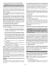
4. Slide economizer into unit and secure with screws. See
Fig. 26.
NOTE: Be sure to engage rear economizer flange under tabs
in vertical return-air opening.
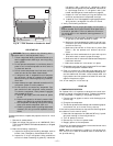
5. Insert economizer plug into economizer harness. Re-
move tape from barometric relief damper. See Fig. 26.
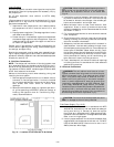
6. If ventilation is not required, proceed to Step 7. If ven-
tilation air is required, perform the following:
a. Make sure the factory-installed jumper is in place
across terminals P and P1 on the economizer logic
module. T and T1 should be disconnected during
adjustment.
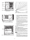
b. The 2 potentiometers with slots for adjustment are
located on the face of the economizer logic module.
Turn the lower potentiometer fully clockwise. The
dampers should be fully closed. Turn the potenti-
ometer gradually counterclockwise until the de-
sired position is reached.
c. Connect T and T1 to the 24V power supply.
MINIMUM
POSITION
OPEN
3
1
T
P
P1
T1
4
2
5
S
S
O
D
C
TR
B
REV. B
198818A
%
H
U
M
I
D
I
T
Y
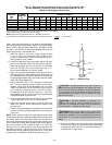
90
70
60
30
10
D
C
B
A
60
65
70
75
55
50
85
80
DAMPER
DAMPER
CLOSED
OPEN
OUTDOOR TEMP.
°F
REV.
97-3672
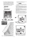
CW–SETPOINTS–CCW
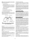
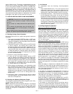
CONTACTS SHOWN IN HIGH ENTHALPY
RUSH AT 24VAC
3 mA MIN. AT 11 VDC
CONTACT RATINGS: 1.5A RUN, 3.5A IN
OR UNPOWERED STATE
1
2
3
TR
TR1
24VAC
ENTHALPY
CONTROL
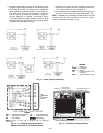
Fig. 23 — Outdoor-Air Thermostat/Enthalpy
Control Installation
LEGEND
OAT — Outdoor-Air Thermostat
NOTE: See unit wiring diagram for details.
Fig. 24 — Wiring Connections for Outdoor-Air
Thermostat
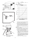
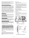
Fig. 25 — Varislide™ Economizer Barometric Relief
Damper Characteristics
—15—