


NOTE: The gas manifold is equipped with a plug located ap-
proximately 5 in. down from the gas valve which may also be
used to connect the manometer.
4. Turn on gas to unit.
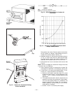
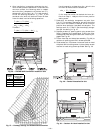
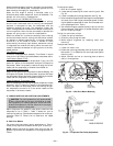
5. Remove cover screw over regulator adjustment screw
on gas valve. See Fig. 31.
6. Adjust regulator adjustment screw for a manifold pres-
sure reading of 3.5 in. wg (high fire on two-stage units).
Turn adjusting screw clockwise to increase manifold pres-
sure, or turn adjusting screw counterclockwise to
decrease manifold pressure.
7. Replace cover screw.
8. Turn off gas to unit.
9. Remove manometer from pressure tap.
10. Replace pipe plug on gas valve or manifold.
11. Turn on gas to unit, and check for leaks.
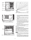
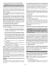
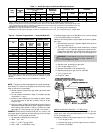
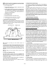
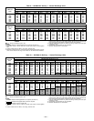
F. Check Burner Flame and Ignition
Observe the unit heating operation. Watch the burner flames
through the access door to see if they are light blue and soft
in appearance and if the flames are approximately the same
for each burner. See Fig. 32.
Main burners are factory set and should require no
adjustment.
To check ignition of main burners and heating controls, move
thermostat set point above room temperature and verify that
the burners light and evaporator fan is energized. Check heat-
ing effect, then lower the thermostat setting below the room
temperature and verify that the burners and evaporator fan
turn off.
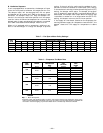
Refer to Table 6 for the correct orifice to use at high
altitudes.
G. Airflow and Temperature Rise
The heating section of each side of unit is designed and
approved for heating operation within the temperature rise
range stamped on the unit rating plate. Temperature rise range
is also found in Table 1.
The heating operation airflow must produce a temperature
rise that falls within the approved range.
Refer to Care and Maintenance section on page 28 to adjust
heating airflow when required.
H. Safety Check of Limit Control
Limit control is located on the deck next to the evaporator
fan. The control shuts off the gas supply and energizes
the evaporator-fan motor and inducer motor if the unit
overheats.
The recommended method of checking this limit control is to
gradually block off the return air after the unit has been
operating for a period of at least 5 minutes. As soon as the
limit control functions, the return-air opening should be un-
blocked to permit normal air circulation. By using this method
to check the limit control, it can be established that the limit
is functioning properly and the unit will ‘‘fail-safe’’ if there is
a restricted circulating air supply or motor failure. If the limit
control does not function during this test, the cause must be
determined and corrected.
I. Heating Sequence of Operation
Heating, Units Without Economizer
When the thermostat calls for heating, terminal W1 is ener-
gized. In order to prevent thermostat short-cycling, the unit
is locked into the Heating mode for at least 1 minute when
W1 is energized. The induced-draft motor is energized and
burner ignition sequence begins. The indoor (evaporator) fan
motor (IFM) is energized 45 seconds after a flame is ignited.
When additional heat is needed, W2 is energized and the high-
fire solenoid on the main gas valve (MGV) is energized. When
the thermostat is satisfied and W1 is deenergized, the IFM
stops after a 45-second time-off delay.
Heating, Units With Economizer
When the thermostat calls for heating, terminal W1 is ener-
gized. In order to prevent thermostat short-cycling, the unit
is locked into the Heating mode for at least 1 minute when
W1 is energized. The induced-draft motor is energized and
the burner ignition sequence begins. The indoor (evaporator)
fan motor (IFM) is energized 45 seconds after a flame is
ignited and the damper moves to the minimum position. If
the two-position damper is used, the outdoor-air damper opens
to the minimum position whenever the evaporator-fan runs.
When additional heat is needed, W2 is energized and the high-
fire solenoid on the main gas valve (MGV) is energized. When
the thermostat is satisfied and W1 is energized, the IFM stops
after a 45-second time-off delay. The economizer damper then
moves to the fully-closed position. When using continuous fan,
the damper will remain in the minimum position.
J. Limit Switches
Heating limit switch (LS) deenergizes the gas valve and the
Integrated Gas Unit Controller (IGC) if the leaving-air tem-
perature exceeds the maximum allowable temperature.
Normally-closed limit switch completes a circuit to the gas
valve. Should the leaving-air temperature rise above the
maximum allowable temperature, the limit switch opens,
instantly closing the gas valve and stopping gas flow to the
burners. The inducer motor and the evaporator motor are en-
ergized to cool heat exchanger.
When the air temperature at the limit switch drops to the
low-temperature setting of the limit switch, the switch closes
and completes the gas valve circuit. The electric-spark igni-
tion system cycles and the unit returns to normal heating
operation.
K. Rollout Switch
Rollout switch (RS) is a temperature-actuated automatic re-
set switch connected in series with heating limit switch. The
function of the switch is to close the main gas valve in the
Fig. 32 — Monoport Burners
—20—