


II. HEATING SECTION START-UP AND ADJUSTMENTS
CAUTION:
Complete the required procedures given
in the Pre-Start-Up section on this page before starting
unit.
Do not jumper any safety devices when operating the unit.
Ensure that burner orifices are properly aligned. Unstable
operation may occur when the burner orifices in the mani-
fold are misaligned.
Follow the lighting instructions on the heating section opera-
tion label (located inside the burner access door) to start the
heating section.
When lighting the unit for the first time, perform the follow-
ing additional steps: If the gas supply pipe was not purged
before connecting the unit, it will be full of air. It is recom-
mended that the ground joint union be loosened and the
supply line be allowed to purge until the odor of gas is de-
tected. Never purge gas lines into a combustion chamber. Im-
mediately upon detection of gas odor, retighten the union. Allow
5 minutes to elapse, then light unit in accordance with Check-
ing Heating Control Operation section below.
A. Checking Heating Control Operation
Start and check the unit for proper heating control operation
as follows: (Also see unit lighting instructions located inside
the burner access panel.)
1. Turn on unit electrical supply and manual gas valve.
2. Set system switch selector at HEAT position and fan switch
at AUTO. or ON position. Set heating temperature
lever above room temperature.
3. The induced-draft motor will start immediately. The evapo-
rator fan will have a 45-second delay before starting.
4. After a call for heating, the main burners should light
within 5 seconds. If the burner does not light, then there
is a 22-second delay before another 5-second try. If the
burner still does not light, the time delay is repeated. If
the burner does not light within 15 minutes, there is a
lockout. To reset the control, break the 24-v power to
W1.
5. The evaporator-fan motor will turn on 45 seconds after
burner ignition.
6. The evaporator-fan motor will turn off 45 seconds after
thermostat temperature is satisfied.
7. Adjust airflow to obtain a temperature rise within the
range specified on the unit nameplate.
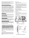
NOTE: The default value for the evaporator-fan motor ON/
OFF delay is 45 seconds. The Integrated Gas Unit Controller
(IGC) modifies this value when abnormal limit switch cycles
occur. Based upon unit operating conditions, the ON delay
can be reduced to 0 seconds and the OFF delay can be ex-
tended to 180 seconds. When one flash of the light-emitting
diode (LED) is observed, the evaporator-fan ON/OFF delay
has been modified.
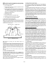
If the limit switch trips at the start of the heating cycle dur-
ing the evaporator ON delay, the time period of the ON delay
for the next cycle will be 5 seconds less than the time at which
the switch tripped.
EXAMPLE: If the limit switch trips at 30 seconds, the
evaporator-fan ON delay for the next cycle will occur at
25 seconds.
To prevent short-cycling, a 5-second reduction will only occur
if a minimum of 10 minutes has elapsed since the last call
for heating.
The evaporator-fan OFF delay can also be modified. Once
the call for heating has ended, there is a 10 minute period
during which the modification can occur. If the limit switch
trips during this period, the evaporator-fan OFF delay will
increase by 15 seconds. A maximum of 9 trips can occur, ex-
tending the evaporator-fan OFF delay to 180 seconds.
To restore the original default value, reset the power to the
unit.
To shut off unit set system switch selector at OFF position.
Resetting heating selector lever below room temperature will
temporarily shut unit off until space temperature falls below
thermostat setting.
B. Safety Relief
A soft solder joint at the suction service Schrader port pro-
vides pressure relief under abnormal temperature and pres-
sure conditions.
C. Ventilation (Continuous Fan)
Set fan and system switch selectors at ON and OFF posi-
tions, respectively. Evaporator fan operates continuously to
provide constant air circulation. When the evaporator-fan
selector switch is turned to the OFF position, there is a
30-second delay before the fan turns off.
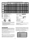
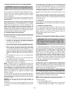
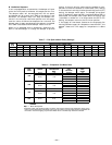
D. Gas Input
Check gas input and manifold pressure after unit start-up.
(See Table 5.) If adjustment is required proceed as follows.
CAUTION:
These units are designed to consume
the rated gas inputs using the fixed orifices at speci-
fied manifold pressures as shown in Table 5. DO
NOT REDRILL THE ORIFICES UNDER ANY
CIRCUMSTANCES.
The rated gas inputs shown in Table 5 are for altitudes from
sea level up to 2000 ft above sea level. These inputs are based
on natural gas with a heating value of 1050 Btu/ft
3
at
0.65 specific gravity, or LP gas with a heating value of
2500 Btu/ft
3
at 1.5 specific gravity. For elevations above
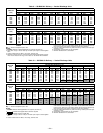
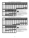
2000 ft, reduce input 4% for each 1000 ft above sea level. When
the gas supply being used has a different heating value or
specific gravity, refer to national and local codes, or contact
your distributor or branch to determine the required orifice
size. Refer to Table 6 for the correct orifice to use at high al-
titudes. Kits are available from your distributor.
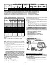
E. Adjusting Gas Input
The gas input to the unit is determined by measuring the
gas flow at the meter or by measuring the manifold pressure.
Measuring the gas flow at the meter is recommended for natu-
ral gas units. The manifold pressure must be measured to
determine the input of propane gas units.
Measuring Gas Flow at Meter Method — Natural Gas Units
Minor adjustment can be made by changing the manifold pres-
sure. The manifold pressure must be maintained between 3.2
and 3.8 in. wg on high-fire, two-stage units. If larger adjust-
ments are required, change main burner orifices following the
recommendations of national and local codes.
NOTE: All other appliances that use the same meter must
be turned off when gas flow is measured at the meter.
Proceed as follows:
1. Turn off gas supply to unit.
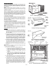
2. Remove pipe plug on outlet of gas valve or manifold, then
connect manometer at this point. Turn on gas to unit.
—18—