


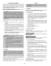
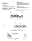
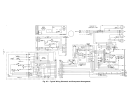
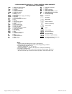

LEGEND AND NOTES FOR FIG. 45 — TYPICAL CONTROL WIRING SCHEMATIC
AND COMPONENT ARRANGEMENT
AHA — Adjustable Heat Anticipator
C—Contactor, Compressor
CAP — Capacitor
CC — Cooling Compensator
CLO — Compressor Lockout
COMP — Compressor Motor
D—Diode
EC — Enthalpy Control
ECON — Economizer
EPS — Emergency Power Supply (9-V Battery)
EQUIP — Equipment
ER — Economizer Relay
FPT — Freeze-Protection Thermostat
FU — Fuse
GND — Ground
HPS — High-Pressure Switch
HS — Hall Effect Sensor
I—Ignitor
IDM — Induced Draft Motor
IFC — Indoor-Fan Contactor
IFM — Indoor-Fan Motor
IGC — Integrated Gas Unit Controller
LPS — Low-Pressure Switch
LS — Limit Switch
MGV — Main Gas Valve
MTR — Motor
OAT — Outdoor-Air Thermostat
OFM — Outdoor-Fan Motor
P—Plug
PL — Plug Assembly
QT — Quadruple Terminal
R—Relay
RS — Rollout Switch
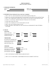
NOTES:
1. Replace original wire with type 90 C wire or its equivalent.
2. Three-phase motors are protected under primary single-phasing conditions.
3. Use thermostats: HH07AT170,172
Subbases: HH93AZ176, 177, 178, and 179
4. Set heat anticipator at .14 amp for first stage and .14 amp for second stage.
5. Use copper conductors only.
6. TRAN is wired for 230 V unit. If unit is to be run with 208 V power supply, disconnect
BLK wire from 230 V tap and connect to 208 V tap (RED). Insulate end of 230 V tap.
SAT — Supply-Air Thermostat
SEN — Sensor
SW1 — Switch Fully Open
SW2 — Switch Fully Closed
SW3 — Switch Minimum Vent Position
SW4 — Switch Maximum Vent Position
TC — Thermostat-Cooling
TH — Thermostat-Heating
TRAN — Transformer
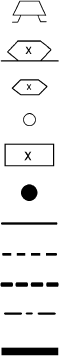
Field Splice
Marked Wire
Terminal (Marked)
Terminal (Unmarked)
Terminal Block
Splice
Factory Wiring
Field Control Wiring
Field Power Wiring
Accessory or Optional Wiring
To indicate common potential only,
not to represent wiring.
Copyright 1998 Bryant Heating & Cooling Systems CATALOG NO. 5358-100