


When the second stage of cooling is satisfied, the compressor
and OFM will be deenergized. The damper position will be
determined by the supply-air temperature.
When the first stage of cooling is satisfied, there is a
30-second delay before evaporator shuts off (036-060). The
damper will move to fully closed position.
Cooling, Units with PARABLADE Economizer
When the outdoor-air is above the enthalpy control setting,
and the room thermostat calls for cooling, the compressor
contactor is energized to start the compressor and the
condenser (outdoor) fan motor. The evaporator (indoor) fan
motor is energized and the economizer damper moves to the
minimum position. After the room thermostat is satisfied the
damper will spring return to the full closed position.
When the outdoor-air is below the enthalpy control setting
and the thermostat calls for cooling, the economizer outdoor
air damper is opened proportionally to maintain between
50 and 56 F at the mixed air sensor. If outside air alone
cannot satisfy the cooling requirements, economizer cooling
is integrated with mechanical cooling. When the room ther-
mostat is satisfied, the damper will spring return to the fully
closed position.
Time Guard II Device
If the unit is equipped with accessory Time Guard II recycle
timer, the unit will delay 5 minutes between compressor starts.
Low-Pressure Switch (LPS)
When the liquid line pressure drops below 7 psig, the LPS
opens 24-v power to the compressor contactor and stops the
compressor. When the pressure reaches 22 psig, the switch
resets and the compressor is allowed to come back on.
High-Pressure Switch (HPS)
When the refrigerant high-side pressure reaches 428 psig, the
HPS opens 24-v power to the compressor contactor and stops
the compressor. When the pressure drops to 320 psig, the switch
resets and the compressor is allowed to restart.
Freeze Protection Thermostat (FPT)
When the evaporator coil leaving refrigerant temperature drops
below 30 F, the FPT opens 24-v power to the compressor con-
tactor and stops the compressor. When the leaving refriger-
ant temperature warms to 45 F, the switch resets and the
compressor is allowed to restart.
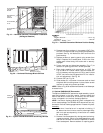
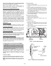
IV. INDOOR AIRFLOW AND AIRFLOW ADJUSTMENTS
CAUTION:
For cooling operation, the recommended
airflow is 300 to 500 cfm per each 12,000 Btuh of rated
cooling capacity. For heating operation, the airflow must
produce a temperature rise that falls within the range
stamped on the unit rating plate.
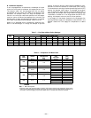
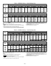
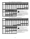
Adjust evaporator-fan speed to meet jobsite conditions and
temperature rise in Table 1. Table 7 shows fan rpm at
motor pulley settings. Table 8 shows evaporator-fan motor per-
formance. Refer to Tables 9-16 to determine fan speed
settings.
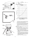
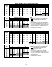
A. Belt Drive Motors
Fan motor pulleys are factory set for speed shown in Table 1.
Check pulley alignment and belt tension prior to start-up.
NOTE: Before adjusting fan speed, make sure the new fan
speed will provide an air temperature rise range as shown in
Table 1.
To change fan speed:
1. Shut off unit power supply.
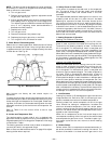
2. Loosen belt by loosening fan motor mounting nuts. See
Fig. 33.
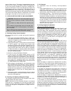
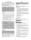
3. Loosen movable pulley flange setscrew (see Fig. 34).
4. Screw movable flange toward fixed flange to increase speed
and away from fixed flange to decrease speed. Increas-
ing fan speed increases load on motor. Do not exceed maxi-
mum speed specified in Table 1.
5. Set movable flange at nearest keyway of pulley hub and
tighten setscrew. (See Table 1 for speed change for each
full turn of pulley flange.)
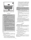
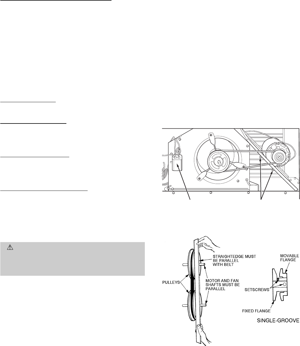
To align fan and motor pulleys:
1. Loosen fan pulley setscrews.
2. Slide fan pulley along fan shaft.
3. Make angular alignment by loosening motor from
mounting.
To adjust belt tension:
1. Loosen fan motor nuts.
2. Slide motor mounting plate away from fan scroll for proper
belt tension (
1
⁄
2
-in. deflection with one finger) and tighten
mounting nuts.
3. Adjust lock bolt and nut on mounting plate to secure
motor in fixed position.
CAPACITOR
(581B036, 048
SINGLE-PHASE
UNITS ONLY)
MOTOR
MOUNTING
PLATE NUTS
Fig. 33 — Belt Drive Motor Mounting
Fig. 34 — Evaporator-Fan Pulley Adjustment
—22—