


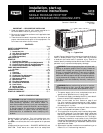
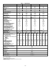
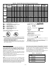
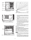
Table 2 — Maximum Gas Flow Capacity of Pipe in Cubic Ft of Gas Per Hour
for Gas Pressures of 0.5 Psig or Less and a Pressure Drop of 0.5 in. wg
(Based on a 0.60 Specific Gravity Gas)
NOMINAL
IRON PIPE
SIZE
(in.)
INTERNAL
DIAMETER
(in.)
LENGTH OF PIPE, FT*
10 20 30 40 50 60 70 80 90 100 125 150 175 200
1
⁄
2
.622 175 120 97 82 73 66 61 57 53 50 44 40 — —
3
⁄
4
.824 360 250 200 170 151 138 125 118 110 103 93 84 77 72
1 1.049 680 465 375 320 285 260 240 220 205 195 175 160 145 135
1
1
⁄
4
1.380 1400 950 770 600 580 530 490 460 430 400 360 325 300 280
1
1
⁄
2
1.610 2100 1460 1180 990 900 810 750 690 650 620 550 500 460 430
Refer to Table 10-2, National Fire Protection Association (NFPA), latest edition.
*This length includes an ordinary number of fittings.
NOTE: Typical natural gas heating value is 1000 Btuh per cubic ft.
115,000
For example: A 115,000 Btuh input unit equals 115 cubic ft per hour or = 115 cubic ft/hr.
1,000
When installing the gas supply line, observe local codes per-
taining to gas pipe installations. Refer to the NFGC ANSI
Z223.1-1992 (in Canada, CAN/CGA B149.1, [2]-M86) or NFPA
54-1992, in the absence of local building codes. Adhere to the
following pertinent recommendations:
1. Avoid low spots in long runs of pipe. Grade all pipe
1
⁄
4
inch in every 15 ft to prevent traps. Grade all hori-
zontal runs downward to risers. Use risers to connect to
heating section and to meter.
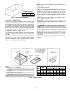
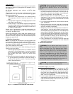
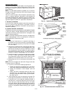
2. Protect all segments of piping system against physical
and thermal damage. Support all piping with appropri-
ate straps, hangers, etc. Use a minimum of one hanger
every 6 ft. See Fig. 10. For pipe sizes larger than
1
⁄
2
in.,
follow recommendations of national codes.
3. Apply joint compound (pipe dope) sparingly and only to
male threads of joint when making pipe connections. Use
only pipe dope that is resistant to action of liquefied pe-
troleum gases as specified by local and/or national codes.
Never use Teflon-coated tape.
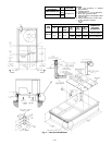
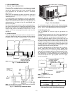
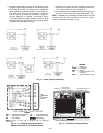
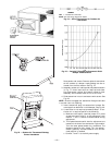
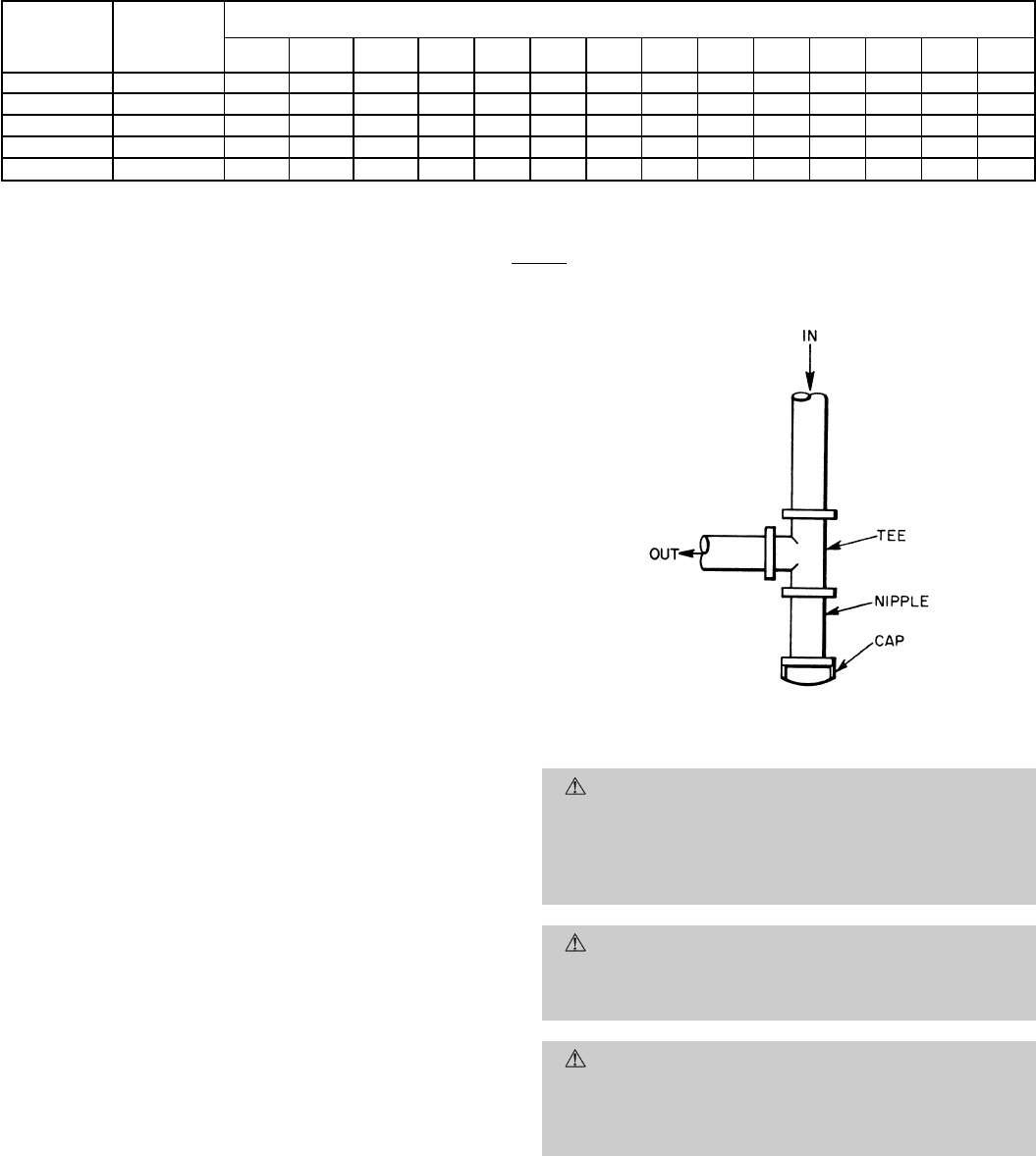
4. Install sediment trap in riser leading to heating sec-
tion. This drip leg functions as a trap for dirt and con-
densate. Install trap where condensate can not freeze.
Install this sediment trap by connecting a piping tee to
riser leading to heating section, so that straight-
through section of tee is vertical. See Fig. 11. Then, con-
nect capped nipple into lower end of tee. Extend capped
nipple below level of gas controls.
5. Install an accessible, external, manual main shut-off valve
in gas supply pipe within 6 ft of heating section.
6. Install ground-joint union close to heating section be-
tween unit manual shutoff and external manual main
shut-off valve.
7. Pressure-test all gas piping in accordance with local and
national plumbing and gas codes before connecting pip-
ing to unit.
NOTE: When pressure testing the gas supply system after
the gas supply piping has been connected to the unit gas valve,
the supply piping must be disconnected from the gas valve
during any pressure testing of the piping systems at test pres-
sure in excess of 0.5 psig. When pressure testing the gas sup-
ply piping system at test pressures equal to or less than
0.5 psig, the unit heating section must be isolated from the
gas piping system by closing the external main manual shut-
off valve and slightly opening the ground-joint union. After
pressure test is completed, retighten ground-joint union.
CAUTION:
Unstable operation may occur when the
gas valve and manifold assembly are forced out of po-
sition while connecting improperly routed rigid gas pip-
ing to the gas valve. Use a backup wrench when mak-
ing connection to avoid strain on, or distortion of, the
gas control piping.
CAUTION:
If a flexible conductor is required or al-
lowed by the authority having jurisdiction, black iron
pipe shall be installed at the gas valve and extend a
minimum of 9 in. outside the unit casing.
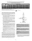
WARNING:
Never use a match or other open flame
when checking for gas leaks. Never purge gas line into
combustion chamber. Failure to adhere to this warning
could result in an explosion causing personal injury or
death.
8. Check for gas leaks at all field- and factory-installed gas
lines after all piping connections have been completed.
Use soap-and-water solution (or method specified by lo-
cal codes and/or regulations).
Fig. 11 — Sediment Trap
—8—