


4. Slide the motor and blower wheel assembly out of the
blower housing. The blower wheel can be cleaned at this
point. If additional cleaning is required, continue with
steps 5 and 6.
5. To remove blower from the motor shaft, remove
2 setscrews.
6. To remove motor, remove 4 screws that hold the motor
to mounting plate. Remove the motor cooling fan by
removing one setscrew. Then remove nuts that hold
motor to mounting plate.
7. To reinstall, reverse the procedure outlined above.
IX. LIMIT SWITCH
Remove blower access panel (Fig. 2). Limit switch is located
on the fan deck.
X. BURNER IGNITION
Unit is equipped with a direct spark ignition 100% lockout
system. Integrated Gas Unit Controller (IGC) is located in
the control box (Fig. 15). The IGC contains a self-diagnostic
LED (light-emitting diode). A single LED on the IGC pro-
vides a visual display of operational or sequential problems
when the power supply is uninterrupted. When a break in
power occurs, the IGC will be reset (resulting in a loss of fault
history). The indoor (evaporator) fan ON/OFF times will also
be reset. The LED error code can be observed through the
viewport. During servicing refer to the label on the control
box cover or Table 17 for an explanation of LED error code
descriptions.
If lockout occurs, unit may be reset by interrupting the power
supply to unit for at least 5 seconds.
CAUTION:
When servicing gas train, do not hit or
plug orifice spuds.
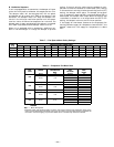
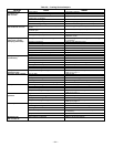
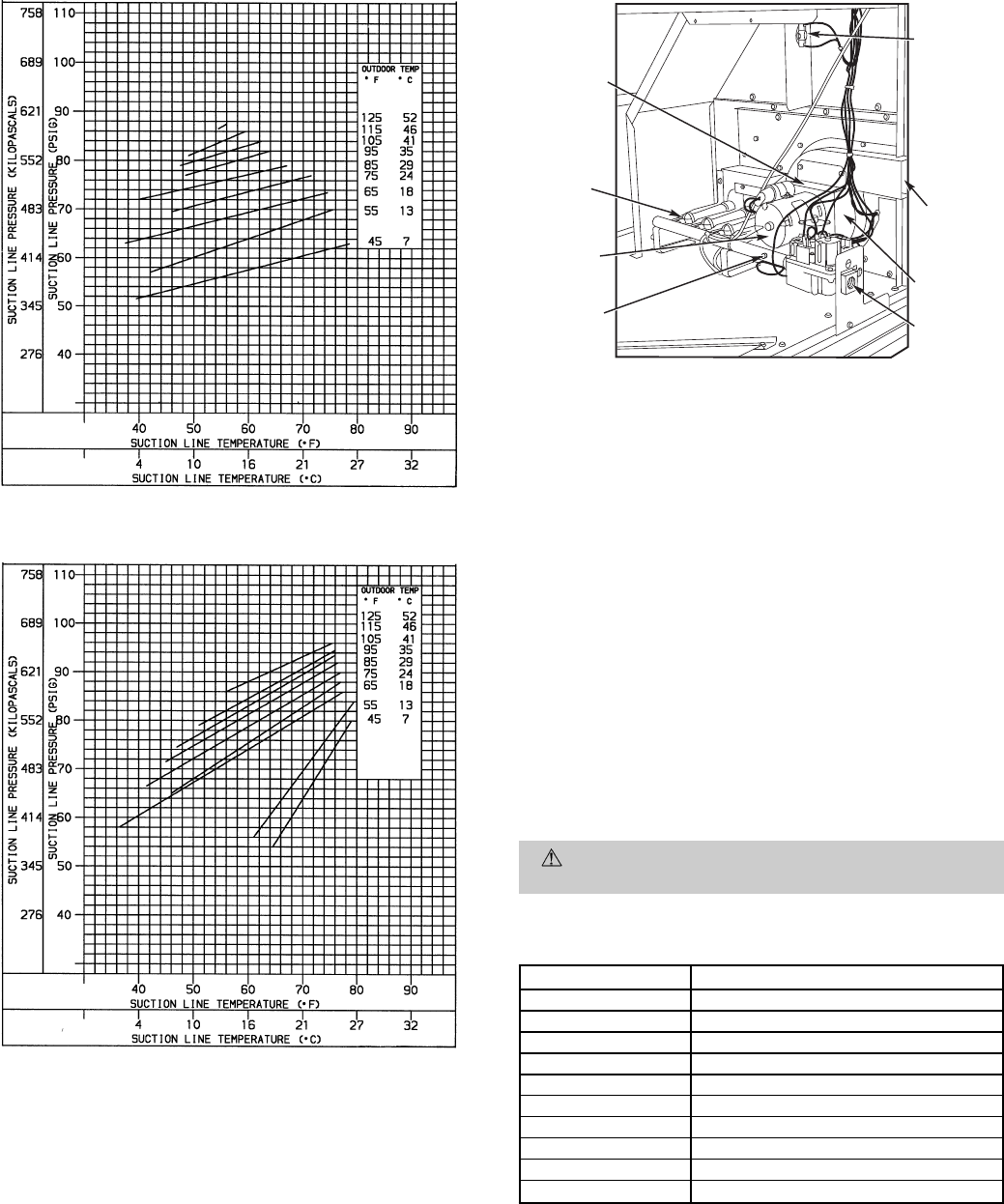
Table 17 — LED Error Code Description*
LED INDICATION ERROR CODE DESCRIPTION
ON Normal Operation
OFF Hardware Failure
1 Flash† Evaporator Fan On/Off Delay Modified
2 Flashes Limit Switch Fault
3 Flashes Flame Sense Fault
4 Flashes 4 Consecutive Limit Switch Faults
5 Flashes Ignition Lockout Fault
6 Flashes Induced-Draft Motor Fault
7 Flashes Rollout Switch Fault
8 Flashes Internal Control Fault
LEGEND
LED — Light-Emitting Diode
*A 3-second pause exists between LED error code flashes. If more than
one error code exists, all applicable codes will be displayed in numeri-
cal sequence.
†Indicates a code that is not an error. The unit will continue to operate
when this code is displayed.
IMPORTANT: Refer to Troubleshooting Tables 18-22 for additional
information.
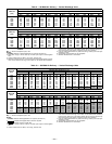
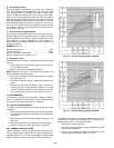
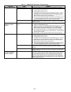
Fig. 41 — Cooling Charging Chart, 581B060
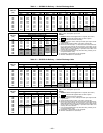
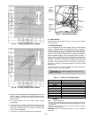
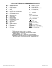
Fig. 42 — Cooling Charging Chart, 581B072
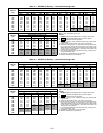
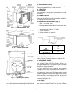
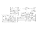
INDUCED-
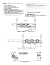
DRAFT
MOTOR
MOUNTING
PLATE
INDUCED-
DRAFT
MOTOR
MANIFOLD
PRESSURE
TAP
FLUE
EXHAUST
ROLLOUT
SWITCH
BLOWER
HOUSING
GAS
VALVE
BURNER
SECTION
Fig. 43 — Burner Section Details
—31—