


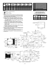
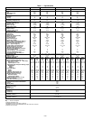
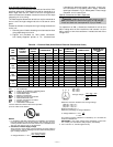
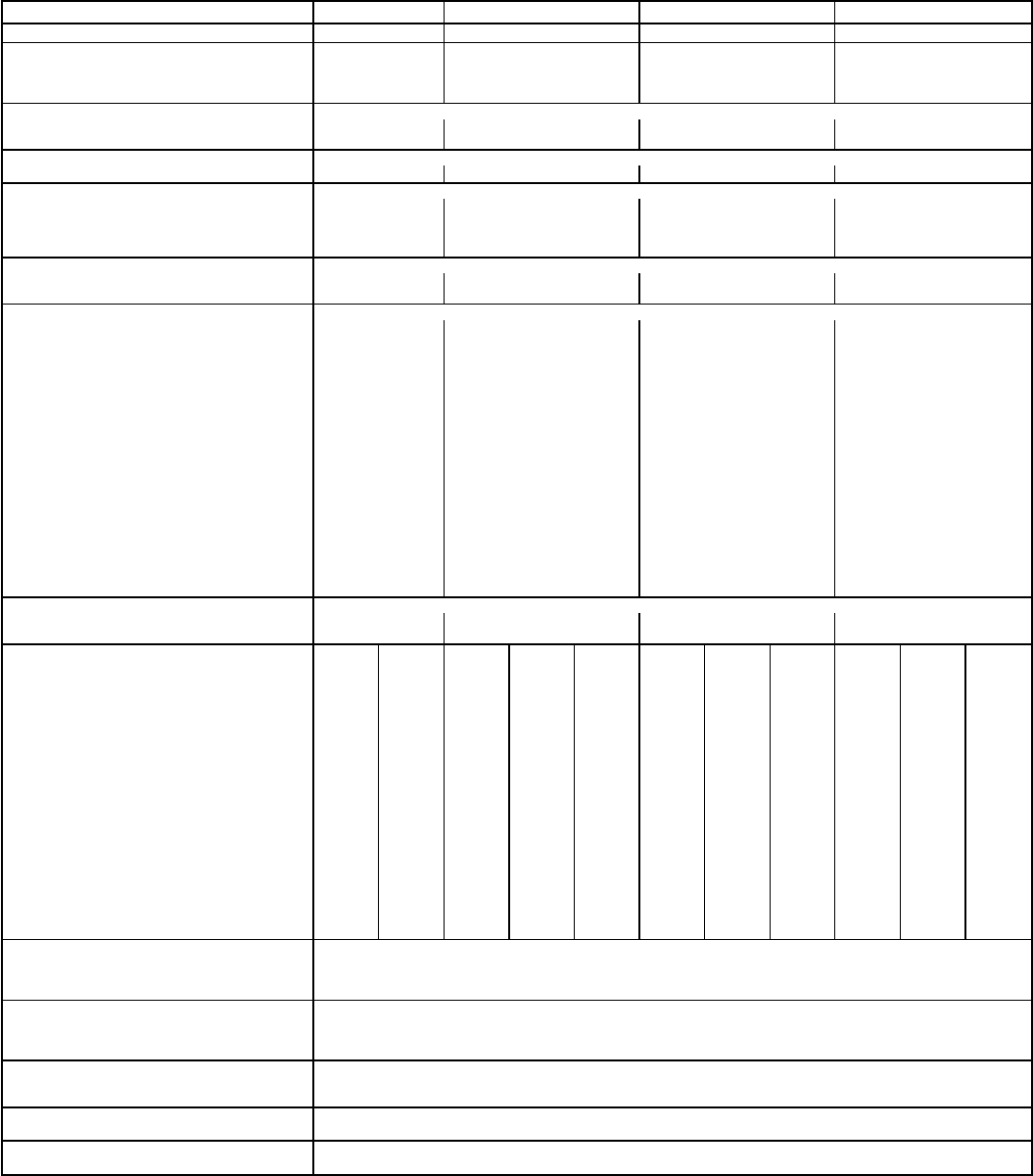
Table 1 — Specifications
BASE UNIT 581B 036 048 060 072
NOMINAL CAPACITY (tons) 3456
OPERATING WEIGHT (lb)
Unit 530 540 560 615
With Economizer 564 574 594 649
Roof Curb 115 115 115 115
COMPRESSOR Scroll
Quantity 1111
Oil (oz) 42 53 50 60
REFRIGERANT TYPE R-22
Operating Charge (lb-oz) 5-8 8-6 10.0 9-10
CONDENSER FAN Propeller
Quantity...Diameter (in.) 1...22 1...22 1...22 1...22
Nominal Cfm 3000 3000 4000 4000
Motor Hp...Rpm
1
⁄
8
...825
1
⁄
8
...825
1
⁄
4
...1100
1
⁄
4
...1100
Watts Input (Total) 180 180 300 300
CONDENSER COIL Enhanced Copper Tubes, Aluminum Lanced Fins
Rows...Fins/in. 1...17 2...17 2...17 2...17
Total Face Area (sq ft) 14.58 16.53 16.53 16.53
EVAPORATOR FAN Centrifugal
Size (in.) 10x10 10x10 10x10 10x10
Type Drive Belt Belt Belt Belt
Nominal Cfm 1200 1600 2000 2400
Maximum Continuous Bhp 1.20 1.20 1.80 2.40
Motor Frame Size 48 48 56 56
Fan Rpm Range 760-1090 840-1185 1020-1460 1120-1585
Motor Bearing Type Ball Ball Ball Ball
Maximum Fan Rpm 2100 2100 2100 2100
Motor Pulley Pitch Diameter A/B (in.) 1.9/2.9 1.9/2.9 2.4/3.4 2.4/3.4
Nominal Motor Shaft Diameter (in.)
1
⁄
2
1
⁄
2
1
⁄
2
5
⁄
8
Fan Pulley Pitch Diameter (in.) 4.5 4.0 4.0 3.7
Belt — Type...Length (in.) A...33 A...36 A...40 A...38
Pulley Center Line Distance (in.) 10.0-12.4 10.0-12.4 14.7-15.5 14.7-15.5
Speed Change Per Full Turn of
Movable Pulley Flange (rpm)
65 70 75 93
Movable Pulley Maximum Full Turns
from Closed Position
5555
Factory Setting — Full Turns Open 3333
Factory Speed Setting (rpm) 890 980 1240 1305
Fan Shaft Diameter at Pulley (in.)
5
⁄
8
5
⁄
8
5
⁄
8
5
⁄
8
EVAPORATOR COIL Enhanced Copper Tubes, Aluminum Double Wavy Fins, Acutrol™ Feed Device
Rows...Fins/in. 2...15 2...15 4...15 4...15
Total Face Area (sq ft) 5.5 5.5 5.5 5.5
FURNACE SECTION Medium
Heat
High
Heat
Low
Heat
Medium
Heat
High
Heat
Low
Heat
Medium
Heat
High
Heat
Low
Heat
Medium
Heat
High
Heat
Rollout Switch Cutout Temp (F)* 195 195 195 195 195 195 195 195 195 195 195
Burner Orifice Diameter (in. ...drill size)†
Natural Gas — Std .113...33 .113...33 .113...33 .113...33 .129...30 .113...33 .113...33 .129...30 .113...33 .113...33 .129...30
Liquid Propane — Alt** .089...43 .089...43 .089...43 .089...43 .102...38 .089...43 .089...43 .102...38 .089...43 .089...43 .102...38
Thermostat Heat Anticipator Setting (amps)
208/230/460 v
Stage 1 .14 .14 .14 .14 .14 .14 .14 .14 .14 .14 .14
Stage 2 .14 .14 .14 .14 .14 .14 .14 .14 .14 .14 .14
Gas Input (Btuh)
Stage 1 50,000 82,000 50,000 82,000 120,000 50,000 82,000 120,000 50,000 82,000 120,000
Stage 2 72,000 115,000 72,000 115,000 150,000 72,000 115,000 150,000 72,000 115,000 150,000
Efficiency (Steady State) (%) 82 80 82 81 80 82 81 80 82 81 80
Temperature Rise Range (F) 15-45 55-85 15-45 35-65 50-80 15-45 35-65 50-80 15-45 35-65 50-80
Manifold Pressure (in. wg)
Natural Gas (Std) 3.5 3.5 3.5 3.5 3.5 3.5 3.5 3.5 3.5 3.5 3.5
Liquid Propane (Alt)** 3.5 3.5 3.5 3.5 3.5 3.5 3.5 3.5 3.5 3.5 3.5
Maximum Static Pressure (in. wg) 1.0 1.0 1.0 1.0 1.0 1.0 1.0 1.0 1.0 1.0 1.0
Gas Valve Quantity 11111111111
Field Gas Connection Size (in.)
1
⁄
2
1
⁄
2
1
⁄
2
1
⁄
2
1
⁄
2
1
⁄
2
1
⁄
2
1
⁄
2
1
⁄
2
1
⁄
2
1
⁄
2
HIGH-PRESSURE SWITCH (psig)
Standard Compressor Internal Relief 450
Cutout 428
Reset (Auto.) 320
LOSS-OF-CHARGE/LOW-PRESSURE SWITCH
(Liquid Line) (psig)
Cutout 7±3
Reset (Auto.) 22±5
FREEZE-PROTECTION THERMOSTAT
Opens (F) 30±5
Closes (F) 45±5
OUTDOOR-AIR INLET SCREENS Cleanable
Quantity...Size (in.) 1...20 x 24 x 1
RETURN-AIR FILTERS Throwaway
Quantity...Size (in.) 2...16 x 25 x 2
LEGEND
Bhp — Brake Horsepower
*Indicates automatic reset.
†581B036072-072072 units have 2 burners.
581B036115-072115 and 581B048150-072150 units have 3 burners.
**Indicates an accessory.
—6—