


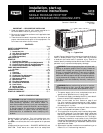
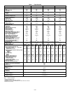
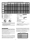
UNIT
581B
STANDARD
UNIT
WEIGHT
VARISLIDE™
ECONOMIZER
WEIGHT
CORNER
WEIGHT
‘‘A’’
CORNER
WEIGHT
‘‘B’’
CORNER
WEIGHT
‘‘C’’
CORNER
WEIGHT
‘‘D’’
Lb Kg Lb Kg Lb Kg Lb Kg Lb Kg Lb Kg
036 530 240 34 15.4 127 57.6 122 55.3 138 62.6 143 64.9
048 540 245 34 15.4 129 58.5 124 56.2 141 64.0 146 66.2
060 560 254 34 15.4 134 60.8 129 58.5 146 66.2 151 68.5
072 615 279 34 15.4 147 66.7 142 64.4 160 72.6 166 75.3
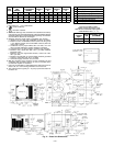
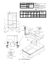
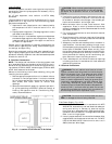
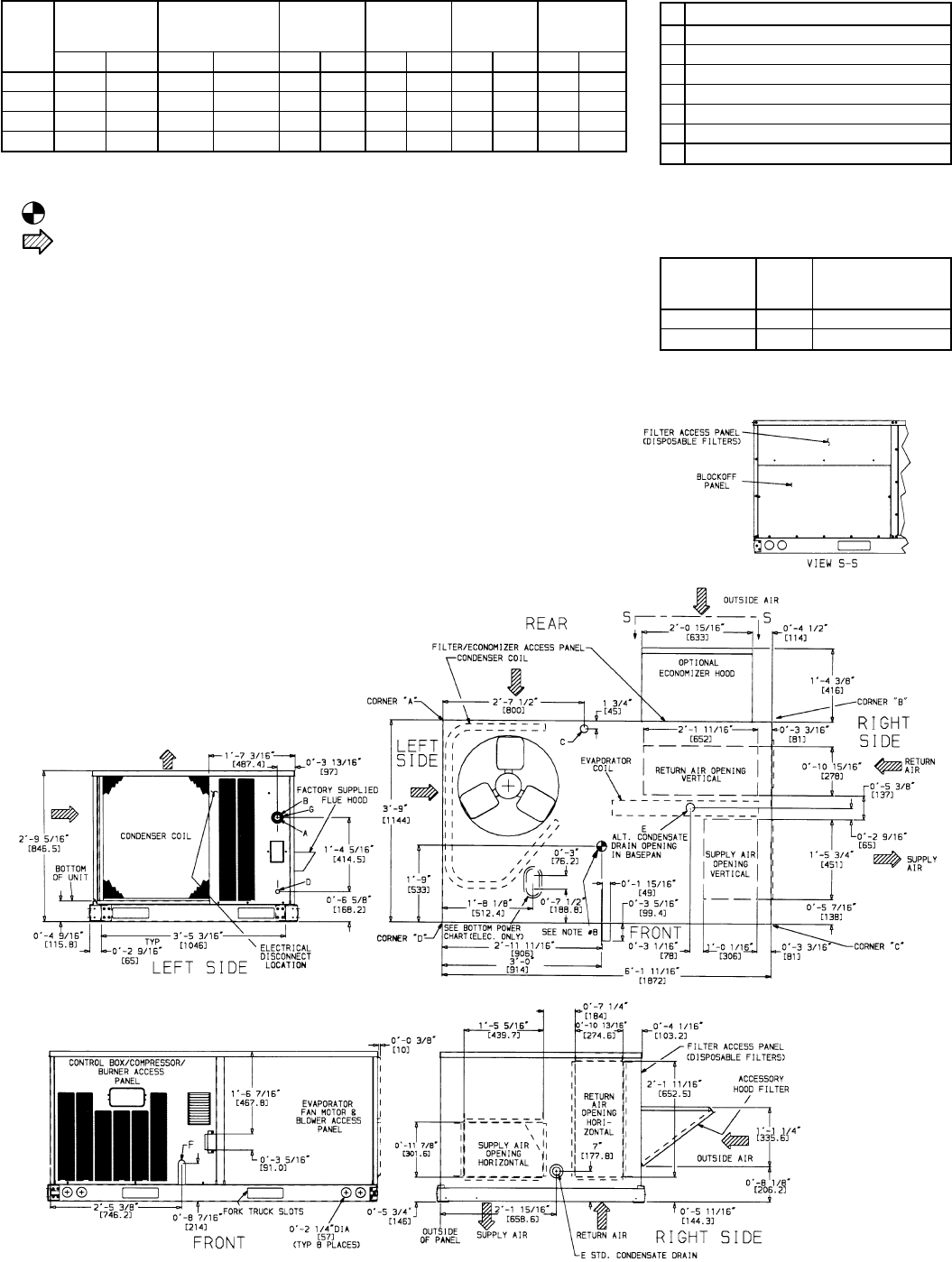
NOTES:
1. Dimensions in [ ] are in millimeters.
2. Center of Gravity.
3. Direction of airflow.
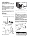
4. On vertical discharge units, ductwork to be attached to accessory
roof curb only. For horizontal discharge units field-supplied flanges
should be attached to horizontal discharge openings, and all duct-
work should be attached to the flanges.
5. Minimum clearance (local codes or jurisdiction may prevail):
a. Between unit, flue side and combustible surfaces, 48 inches.
b. Bottom of unit to combustible surfaces (when not using curb)
1 inch. Bottom of base rail to combustible surfaces (when not
using curb) 0 inches.
c. Condenser coil, for proper airflow, 36 in. one side, 12 in. the
other. The side getting the greater clearance is optional.
d. Overhead, 60 in. to assure proper condenser fan operation.
e. Between units, control box side, 42 in. per NEC (National
Electrical Code).
f. Between unit and ungrounded surfaces, control box side,
36 in. per NEC.
g. Between unit and block or concrete walls and other grounded
surfaces, control box side, 42 in. per NEC.
h. Horizontal supply and return end, 0 inches.
6. With the exception of the clearance for the condenser coil and
combustion side as stated in Note 5a, b, and c, a removable fence
or barricade requires no clearance.
7. Units may be installed on combustible floors made from wood or
Class A, B, or C roof covering material if set on base rail.
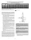
8. The vertical center of gravity is 1Ј-6Љ [457] up from the bottom of
the base rail.
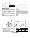
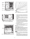
CONNECTION SIZES
A 1
3
⁄
8
Љ Dia. [35] Field Power Supply Hole
B 2Љ Dia. [51] Power Supply Knock-Out
C 1
3
⁄
4
Љ Dia. [44] Charging Port Hole
D
7
⁄
8
Љ Dia. [22] Field Control Wiring Hole
E
3
⁄
4
Љ-14 NPT Condensate Drain
F
1
⁄
2
Љ-14 NPT Gas Connection
G 2
1
⁄
2
Љ Dia. [64] Power Supply Knock-Out
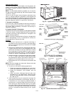
Fig. 2 — Base Unit Dimensions
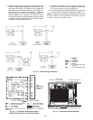
BOTTOM POWER CHART,
THESE HOLES REQUIRED FOR
USE WITH ACCESSORY PACKAGES —
CRBTMPWR001A00 (
1
⁄
2
Љ,
3
⁄
4
Љ)
THREADED
CONDUIT
SIZE
WIRE
USE
REQUIRED SIZES
(MAXIMUM)
1
⁄
2
؆ 24 V
7
⁄
8
Љ [22.2]
3
⁄
4
؆ Power 1
1
⁄
8
Љ [28.4]
—2—