


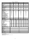
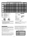
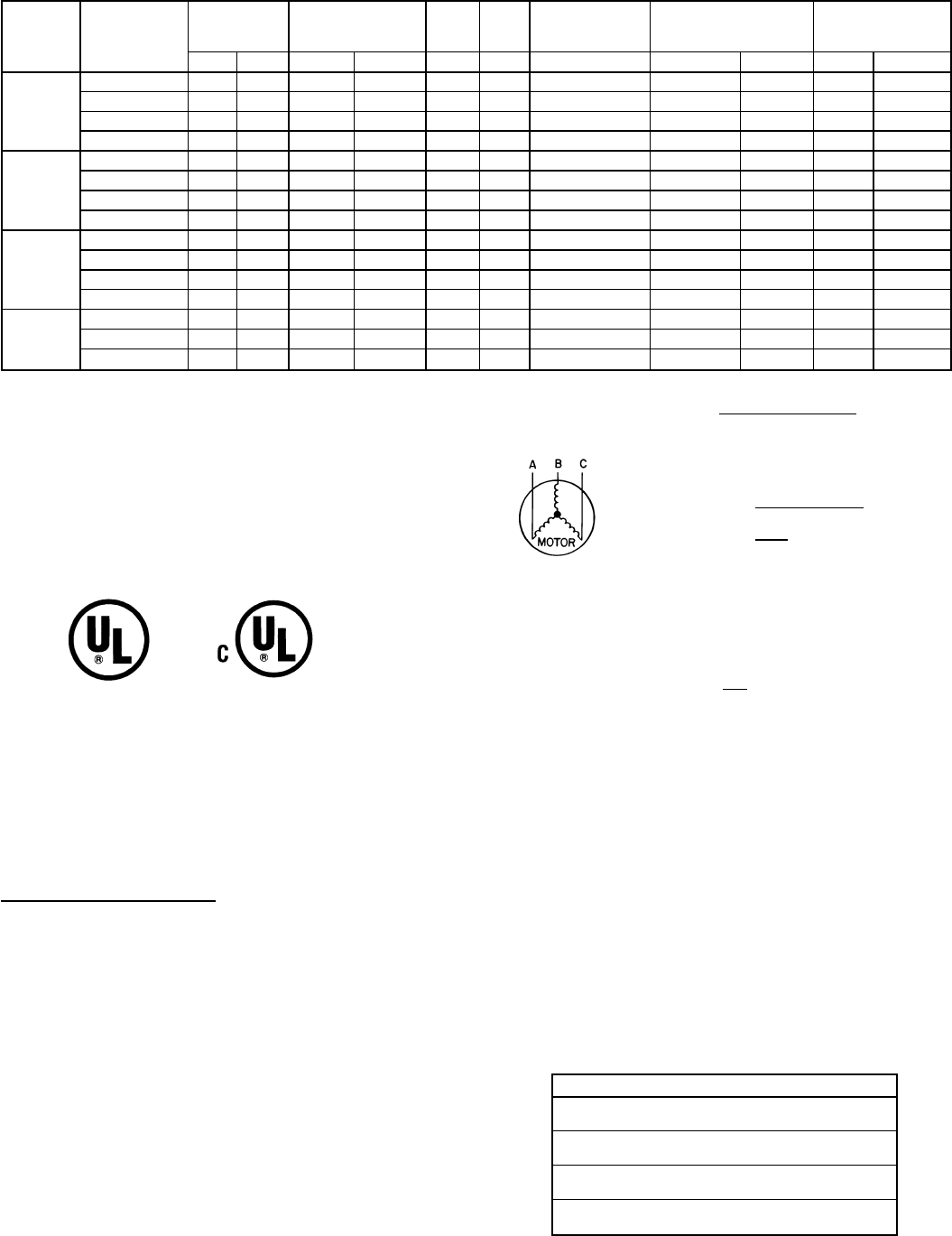
Table 3B — Electrical Data (Units with Electrical Convenience Outlet)
UNIT
581B
NOMINAL
VOLTAGE
(V-Ph-Hz)
VOLTAGE
RANGE
COMPRESSOR OFM IFM
COMBUSTION
FAN MOTOR
POWER SUPPLY
WITH OUTLET
MINIMUM UNIT
DISCONNECT
SIZE*
Min Max RLA LRA FLA FLA FLA MCA MOCP† FLA LRA
036
(3 Tons)
208/230-1-60 187 254 16.0 88.0 0.7 4.9 .57 31.6/31.66 40/40 30/30 106/106
208/230-3-60 187 254 10.3 77.0 0.7 4.9 .57 24.5/24.5 30/30 24/24 95/ 95
460-3-60 414 508 5.1 39.0 0.4 2.2 .30 14.6 20 14 59
575-3-60 518 632 4.2 31.0 0.4 2.2 .30 11.5 15 11 47
048
(4 Tons)
208/230-1-60 187 254 23.7 129.0 0.7 4.9 .57 41.2/41.2 50/50 39/39 147/147
208/230-3-60 187 254 13.5 99.0 0.7 4.9 .57 28.5/28.5 35/35 28/28 117/117
460-3-60 414 508 7.4 49.5 0.4 2.2 .30 14.6 20 14 59
575-3-60 518 632 5.8 40.0 0.4 2.2 .30 11.5 15 11 47
060
(5 Tons)
208/230-1-60 187 254 28.8 169.0 1.5 8.8 .57 52.3/52.3 60/60 51/51 221/221
208/230-3-60 187 254 17.3 123.0 1.5 5.8 .57 34.9/34.9 40/40 34/34 173/173
460-3-60 414 508 9.0 62.0 0.8 2.6 .30 17.4 20 17 87
575-3-60 518 632 7.1 50.0 0.8 2.6 .30 13.8 20 13 61
072
(6 Tons)
208/230-3-60 187 254 20.5 156.0 1.4 5.8 .57 38.8/38.8 45/45 35/35 205/205
460-3-60 414 508 9.6 70.0 0.6 2.6 .30 17.9 20 17 95
575-3-60 518 632 7.7 56.0 0.6 2.6 .30 14.4 20 14 75
LEGEND
CUL — Canadian Underwriters’ Laboratories
FLA — Full Load Amps
HACR — Heating, Air Conditioning and Refrigeration
IFM — Indoor (Evaporator) Fan Motor
LRA — Locked Rotor Amps
MCA — Minimum Circuit Amps
MOCP — Maximum Overcurrent Protection
NEC — National Electrical Code
OFM — Outdoor (Condenser) Fan Motor
RLA — Rated Load Amps
*Used to determine minimum disconnect per NEC.
†Fuse or HACR circuit breaker.
NOTES:
1. In compliance with NEC requirements for multimotor and combina-
tion load equipment (refer to NEC Articles 430 and 440), the over-
current protective device for the unit shall be fuse or HACR breaker.
The CUL units may be fuse or circuit breaker.
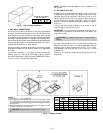
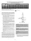
2. Unbalanced 3-Phase Supply Voltage
Never operate a motor where a phase imbalance in supply voltage is
greater than 2%.
Use the following formula to determine the percent-
age of voltage imbalance.
max voltage deviation
from average voltage
% Voltage Imbalance = 100 x
average voltage
EXAMPLE: Supply voltage is 460-3-60.
AB = 452 v
BC = 464 v
AC = 455 v
452 + 464 + 455
Average Voltage =
3
1371
=
3
= 457
Determine maximum deviation from average voltage.
(AB) 457 – 452=5v
(BC) 464 – 457=7v
(AC) 457 – 455=2v
Maximum deviation is 7 v.
Determine percentage of voltage imbalance:
7
% Voltage Imbalance = 100 x
457
= 1.53%
This amount of phase imbalance is satisfactory as it is below the
maximum allowable 2%.
IMPORTANT: If the supply voltage phase imbalance is more than
2%, contact your local electric utility company immediately.
3. 575-v units are CUL approved only.
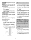
Control Voltage Connections
Install a factory-approved room thermostat. See Table 4. Lo-
cate the thermostat on an inside wall in the space to be con-
ditioned where it will not be subjected to either a cooling or
heating source or direct exposure to sunlight. Mount the ther-
mostat 4 to 5 ft above the floor.
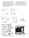
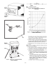
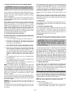
Route thermostat cable or equivalent single leads of colored
wire from subbase terminals through connector on unit to low-
voltage connections (shown in Fig. 14).
Connect thermostat wires to matching screw terminals of low-
voltage connection board. See Fig. 14.
NOTE: For wire runs up to 50 ft, use no. 18 AWG insulated
wire (35 C minimum). For 50 to 75 ft, use no. 16 AWG insu-
lated wire (35 C minimum). For 75 to 155 ft, use no. 14 AWG
insulated wire (35 C minimum). All wire larger than no. 18
AWG cannot be directly connected to the thermostat and will
require a junction box and splice at the thermostat.
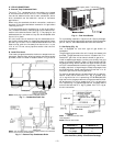
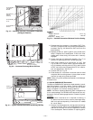
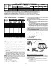
Pass control wires through the hole provided in the corner
post; then feed wires through the raceway built into the cor-
ner post to the 24-v barrier located on the left side of the con-
trol box. See Fig. 15. The raceway provides the UL required
clearance between high- and low-voltage wiring.
Connect thermostat wires to pigtails of low-voltage circuit in
low-voltage section on control box using wirenuts.
Table 4 — Thermostat List*
TYPE
Manual Changeover (Standard)
2 Heat/2 Cool
Auto. Changeover (Standard)
2 Heat/2 Cool
Manual Changeover (Electronic Setback)
2 Heat/2 Cool
Auto. Changeover (Electronic Setback)
2 Heat/2 Cool
*See Trade Prices for part numbers.
—12—