


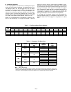

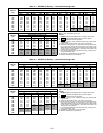
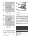
B. Low Charge Cooling
Using Cooling Charging Charts, Fig. 39-42, vary refrigerant
until the conditions of the appropriate chart are met. Note
the charging charts are different from type normally used.
Charts are based on charging the units to the correct super-
heat for the various operating conditions. Accurate pressure
gage and temperature-sensing device are required. Connect
the pressure gage to the service port on the suction line. Mount
the temperature-sensing device on the suction line and insu-
late it so that outdoor ambient temperature does not affect
the reading. Indoor-air cfm must be within the normal oper-
ating range of the unit.
C. To Use Cooling Charging Charts
Take the outdoor ambient temperature and read the suction
pressure gage. Refer to appropriate chart to determine what
suction temperature should be. If suction temperature is high,
add refrigerant. If suction temperature is low, carefully re-
claim some of the charge. Recheck the suction pressure as
charge is adjusted.
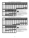
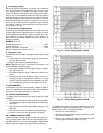
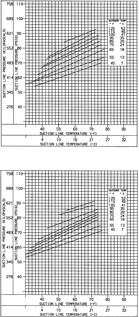
EXAMPLE: (Fig. 41)
Outdoor Temperature ...........................85F
Suction Pressure .............................74psig
Suction Temperature should be ...................48F
(Suction Temperature may vary±5F.)
D. Refrigerant Leaks
Proceed as follows to repair a refrigerant leak and to charge
the unit:
1. Locate leak and ensure that refrigerant system pres-
sure has been relieved.
2. Repair leak following accepted practices.
NOTE: Replace filter drier in the liquid line whenever the
system has been opened for repair.
3. Add a small charge of R-22 refrigerant vapor to system
and leak-test unit.
4. Evacuate refrigerant system if additional leaks are not
found.
5. Charge unit with R-22 refrigerant, using a volumetric-
charging cylinder or accurate scale. Refer to unit rating
plate for required charge. Be sure to add extra refriger-
ant to compensate for internal volume of filter drier.
VI. MAIN BURNERS
At the beginning of each heating season, inspect for deterio-
ration or blockage due to corrosion or other causes. Observe
the main burner flames and adjust if necessary.
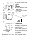
VII. FLUE GAS PASSAGEWAYS
To inspect the flue collector box and upper areas of the heat
exchanger:
1. Remove the combustion blower wheel and motor assem-
bly according to directions in Combustion-Air Blower sec-
tion below.
2. Remove the 3 screws holding the blower housing to the
flue cover.
3. Remove the flue cover to inspect the heat exchanger.
4. Clean all surfaces as required using a wire brush.
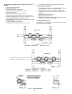
VIII. COMBUSTION-AIR BLOWER
Clean periodically to ensure proper airflow and heating effi-
ciency. Inspect blower wheel every fall and periodically dur-
ing heating season. For the first heating season, inspect blower
wheel bimonthly to determine proper cleaning frequency.
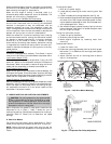
To inspect blower wheel, remove draft hood and screen. Shine
a flashlight into opening to inspect wheel. If cleaning is re-
quired, remove motor and wheel as follows:
1. Slide burner access panel out.
2. Remove the 2 screws which hold the heat shield in place,
and remove heat shield.
3. Remove the 7 screws that attach induced-draft motor
mounting plate to blower housing (Fig. 43).
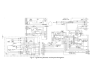
Fig. 39 — Cooling Charging Chart, 581B036
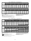
Fig. 40 — Cooling Charging Chart, 581B048
—30—