


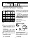
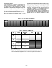
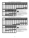

Table 5 — Rated Gas Inputs at Indicated Manifold Pressures
UNIT
581B
NUMBER
OF
ORIFICES
GAS SUPPLY PRESSURE
(in. wg)
MANIFOLD
PRESSURE
(in. wg)
NATURAL GAS PROPANE*
Natural Propane
Orifice
Drill Size
Heating Input
(Btuh)†
Orifice
Drill Size
Heating Input
(Btuh)†
Min Max Min Max Natural Propane
036-072**
2 4.0 13.6 5.0 13.0 3.5 3.5 33 72,000 43 72,000
3 4.0 13.6 5.0 13.0 3.5†† 3.5†† 33 115,000†† 43 115,000††
3 5.0 13.6 5.0 13.0 3.5 3.5 30 150,000 38 150,000
*When a 581B unit is converted to liquid propane (LP), the burners must be modified with accessory LP Kit.
†Based on altitudes from sea level up to 2000 ft above sea level. For altitudes above 2000 ft, reduce input rating 4% for
each 1000 ft above sea level. In Canada, from 2000 ft above sea level to 4,500 ft above sea level, derate the unit 10%.
**581B036 with 150,000 Btuh input not available.
††581B036115 at high fire operation. At low fire, manifold pressure is 1.8 in. wg, and heating input is 82,000 Btuh.
581B048-072150 at high fire operation. At low fire, manifold pressure is 2.2 in. wg, and heating input is 120,000 Btuh.
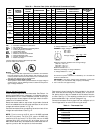
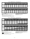
Table 6 — Altitude Compensation* — Units 581B036-072
ELEVATION
(ft)
72,000 AND 115,000
BTUH NOMINAL INPUT
150,000 BTUH
NOMINAL INPUT
Natural
Gas
Orifice
Size†
Liquid
Propane
Orifice
Size†
Natural
Gas
Orifice
Size†
Liquid
Propane
Orifice
Size†
0-2,000 33 43 30 38
2,000 34 43 30 39
3,000 35 44 31 40
4,000 36 44 32 41
5,000 36 44 33 42
6,000 37 45 34 43
7,000 37 45 35 43
8,000 38 46 36 44
9,000 39 47 37 44
10,000 41 48 38 45
11,000 43 48 39 45
12,000 44 49 40 46
13,000 44 49 41 47
14,000 45 50 42 47
*As the height above sea level increases, there is less oxygen per cubic
foot of air. Therefore, heat input rate should be reduced at higher
altitudes.
†Orifices are available through your local distributor or branch.
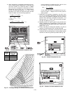
NOTE: The gas manifold is equipped with a plug located ap-
proximately 5 in. down from the gas valve which may also be
used to connect the manometer.
3. Record number of seconds for gas meter test dial to make
one revolution.
4. Divide number of seconds in Step 3 into 3600 (number
of seconds in 1 hour).
5. Multiply result of Step 4 by the number of cubic ft shown
for one revolution of test dial to obtain cubic ft of gas
flow per hour.
6. Multiply result of Step 5 by Btu heating value of gas to
obtain total measured input in Btuh. Compare this value
with heating input shown in Table 1. (Consult the local
gas supplier if the heating value of gas is not known.)
EXAMPLE: Assume that the size of test dial is 1 cubic ft, one
revolution takes 33 seconds, and the heating value of the gas
is 1050 Btu/ft
3
, then proceed as follows:
1. 33 seconds to complete one revolution.
2. 3600 Ϭ 33 = 109
3. 109x1=109ft
3
of gas flow/hr
4. 109 x 1050 = 114,450 Btuh input
If the desired gas input is 115,000 Btuh, only a minor change
in the manifold pressure is required.
Observe manifold pressure and proceed as follows to adjust
gas input:
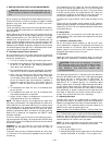
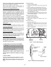
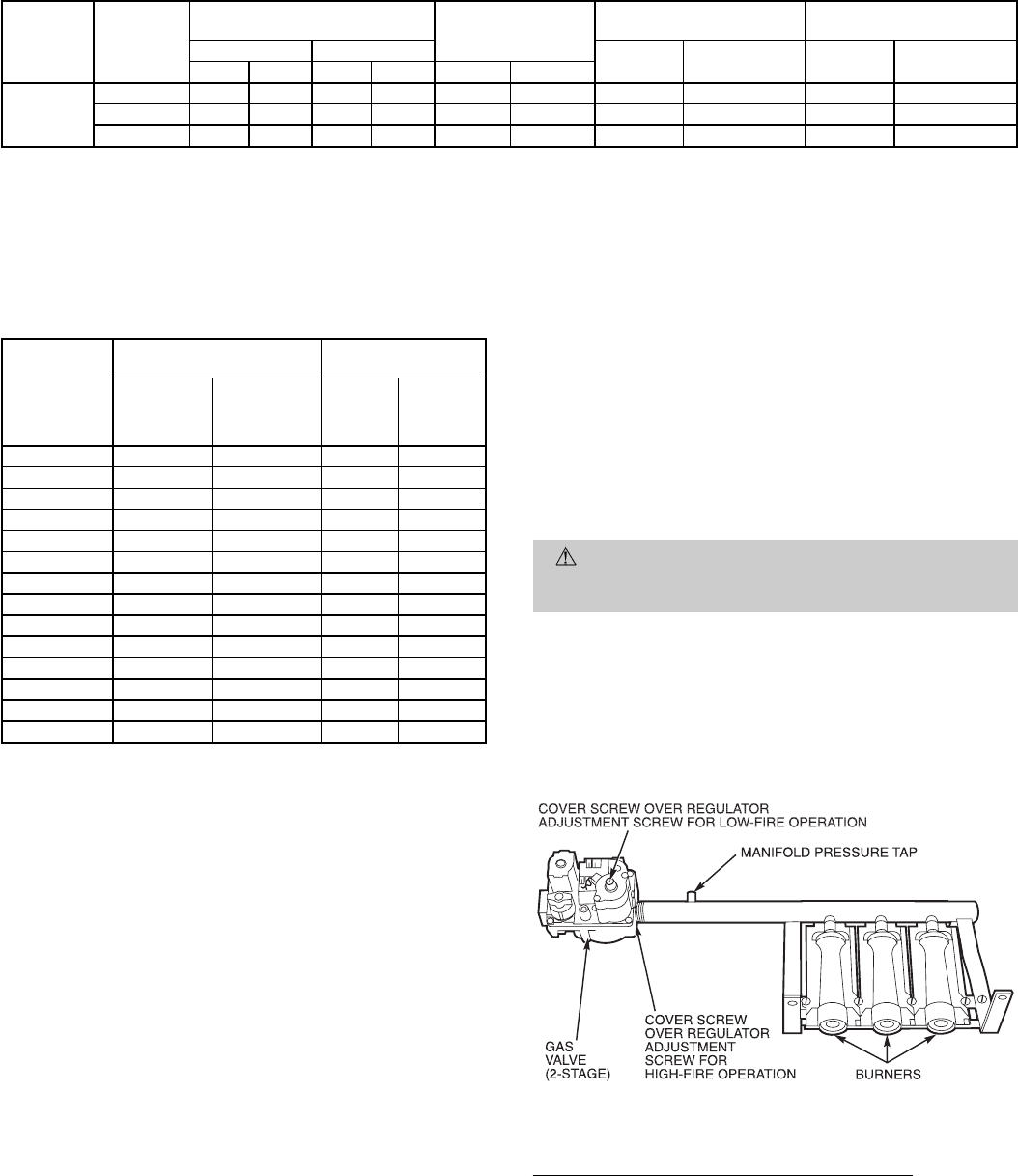
1. Remove cover screw over regulator adjustment screw on
gas valve. See Fig. 31.
2. Turn regulator adjustment screw clockwise to increase
gas input, or turn regulator adjustment screw counter-
clockwise to decrease input. Manifold pressure must be
between 3.2 and 3.8 in. wg on high-fire, two-stage units.
WARNING:
Unsafe operation of the unit may result
if manifold pressure is outside this range. Personal in-
jury or unit damage may result.
3. Replace cover screw cap on gas valve.
4. Turn off gas supply to unit.
5. Remove manometer from pressure tap.
6. Replace pipe plug on gas valve or manifold.
7. Turn on gas to unit.
8. Check for leaks.
Measuring Manifold Pressure — LP Gas Units
The main burner orifices on LP gas unit are sized for the unit
rated input when the manifold pressure is 3.5 in. wg (high-
fire on two-stage units).
Proceed as follows to adjust gas input on an LP gas unit:
1. Turn off gas to unit.
2. Remove pipe plug on outlet of gas valve or manifold.
3. Connect manometer.
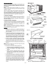
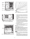
Fig. 31 — Burner Tray Details
—19—