


INSTALLATION
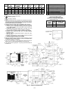
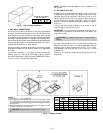
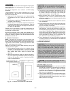
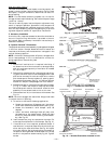
Unit is shipped in the vertical airflow configuration. See
Fig. 1. To convert to horizontal discharge, remove horizontal
duct opening covers. Using the same screws, install covers
with insulation-side down (facing outside) on the unit on ver-
tical duct openings. Seals around duct openings must be tight.
Model 581B meets the California maximum oxides of nitro-
gen (NO
x
) emission regulations when equipped with acces-
sory NO
x
Reduction Kit (part no. 309424-101).
These units are equipped with an energy-saving, automatic,
electric direct spark ignition system that does not have a con-
tinuously burning pilot. All units are manufactured with natu-
ral gas controls.
These units are designed for a minimum continuous return
air temperature of 50 F (dry bulb) or an intermittent opera-
tion down to 45 F (dry bulb), such as when used with a night
set-back thermostat.
All units can be connected into existing duct systems that are
properly sized and designed to handle an airflow of 300 to
500 cfm per each 12,000 Btuh of rated cooling capacity.
NOTE: When installing any accessory or factory-installed op-
tion, see the manufacturer’s installation instructions pack-
aged with the accessory or option. A qualified agency must
use factory-authorized kits or accessories when modifying this
unit.
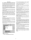
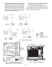
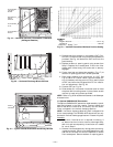
I. LOCATE THE UNIT
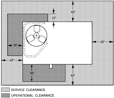
A. Clearance
Maintain clearance around and above unit to provide mini-
mum distance from combustible materials, proper airflow, and
service access. See Fig. 2 and 3.
Minimum clearance to combustibles is 48 in. on flue side; bot-
tom of unit (when not using curb) is 1 inch; bottom of base
rail (when not using curb) is 0 inches.
Minimum clearance on all sides to block walls or any other
grounded surface is 42 inches. Between unit and ungrounded
surfaces, control box side is 36 inches; between units, control
box side, is 42 inches.
Minimum clearance of condenser coil is 36 in. on one side,
12 in. the other. Side getting greater clearance is optional.
Minimum distance overhead is 60 inches.
Locate the unit where the vent cap will be a minimum of 4 ft
from openable windows and doors.
Do not install unit in an indoor location. Do not locate unit
air inlets near exhaust vents or other sources of contami-
nated air.
Be sure that unit is installed so that snow will not block the
combustion intake or flue outlet.
Although unit is weatherproof, guard against water from higher
level runoff and overhangs.
Slab-mounted units should be at least 4 in. above the highest
expected water, flood, and runoff levels. Do not use the unit if
it has been under water.
Locate mechanical draft system flue assembly at least 48 in.
from any opening through which combustion products could
enter the building, and at least 24 in. from an adjacent build-
ing. When unit is located adjacent to public walkways, flue
assembly must be at least 7 ft above grade.
Flue gas can deteriorate building materials. Orient unit such
that flue gas will not affect building materials.
Adequate combustion-air space must be provided for proper
operation of this equipment. Be sure that installation com-
plies with all local codes.
Flue vent discharge must have a minimum horizontal clear-
ance of 4 ft from electric and gas meters, gas regulators, and
gas relief equipment.
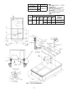
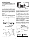
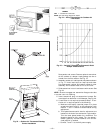
B. Roof Curb Mount
Assemble and install accessory roof curb in accordance with
instructions shipped with curb. See Fig. 4. Install insulation
cant strips, roofing felt, and counter flashing as shown. Duct-
work must be attached to curb. If gas, electric power, or con-
trol power is to be routed through the curb, attach the utility
connection plates to the roof curb in accordance with the ac-
cessory installation instructions. Accessory electric and gas
utility connection plates must be installed before unit is in
place on roof curb.
IMPORTANT: The gasketing of the unit to the roof curb is
critical for a watertight seal. Install gasket with the roof curb
as shown in Fig. 4. Improperly applied gasket can also result
in air leaks and poor unit performance.
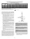
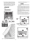
Curb should be level. This is necessary for unit drain to func-
tion properly. Unit leveling tolerances are shown in Fig. 5.
C. Slab Mount (Horizontal Units Only)
Provide a level concrete slab that extends a minimum of 6 in.
beyond unit cabinet. Install a gravel apron in front of condenser-
coil air inlet to prevent grass and foliage from obstructing
airflow.
NOTE: Horizontal units may be installed on a roof curb if
required.
Fig. 3 — Service and Operational Clearances
—3—