


event of flame rollout. The switch is located above the main
burners on the internal wind baffle. When the temperature
at the rollout switch exceeds the maximum allowable tem-
perature, the W control circuit trips, deenergizing the gas valve
and stopping gas flow to the burners. The inducer motor is
energized when the rollout switch trips. Although the rollout
switch has an automatic reset, the IGC locks out the unit when
a trip occurs and must be reset at unit disconnect. If the switch
cycles again, shut down the unit and call for service.
III. COOLING SECTION START-UP AND ADJUSTMENTS
CAUTION:
Complete the required procedures given
in the Pre-Start-Up section on page 17 before starting
the unit.
Do not jumper any safety devices when operating the
unit.
Do not operate the compressor when the outdoor tem-
perature is below 25 F (unless accessory low ambient
kit is installed).
Do not rapid-cycle the compressor. Allow 5 minutes be-
tween ‘‘on’’ cycles to prevent compressor damage.
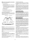
A. Checking Cooling Control Operation
Start and check the unit for proper cooling control operation
as follows:
1. Place room thermostat SYSTEM switch in OFF posi-
tion. Observe that blower motor starts when FAN switch
is placed in ON position and shuts down when FAN switch
is placed in AUTO. position.
2. Place SYSTEM switch in COOL position and FAN switch
in AUTO. position. Set cooling control below room
temperature. Observe that compressor, condenser-fan mo-
tor, and evaporator-fan motor start. Observe that cool-
ing cycle shuts down when control setting is satisfied,
or reset thermostat at a position above room tempera-
ture. Compressor will shut off. Evaporator fan will shut
off after a 30-second delay.
3. Check unit charge. See Section B below.
4. To shut off unit, set system selector switch at OFF
position. Resetting thermostat at a position above room
temperature shuts unit off temporarily until space tem-
perature exceeds thermostat setting. Units are equipped
with Cycle-LOC™ protection device. Unit shuts down
on any safety trip, and indicator light on thermostat comes
on. Check reason for all safety trips.
5. When using an autochangeover room thermostat, place
both SYSTEM and FAN switches in AUTO. positions.
Observe that unit operates in Heating mode when tem-
perature control is set to call for heating (above room
temperature) and operates in Cooling mode when tem-
perature control is set to call for cooling (below room
temperature).
6. Compressor restart is accomplished by manual reset at
the thermostat by turning the selector switch to OFF
and then to ON positions.
B. Checking and Adjusting Refrigerant Charge
The refrigerant system contains R-22 refrigerant, and is fully
charged, tested, and factory-sealed.
NOTE: Adjustment of the refrigerant charge is not required
unless the unit is suspected of not having the proper R-22
charge. This unit uses charging charts to determine proper
charge. See Refrigerant Charge section on page 29 for fur-
ther details.
C. Unit Controls
All compressors have the following internal-protection
controls:
1. High-Pressure Relief Valve — This valve (internal to the
compressor) opens when the pressure differential be-
tween the low and high side becomes excessive and will
automatically reset when pressure returns to normal.
2. Compressor Overload — This overload interrupts power
to the compressor when either the current or internal
temperature become excessive, and automatically re-
sets when the internal temperature drops to a safe level.
This overload may require up to 60 minutes (or longer)
to reset; therefore, if the internal overload is suspected
of being open, disconnect the electrical power to the unit
and check the circuit through the overload with an ohm-
meter or continuity tester.
D. Cooling Sequence of Operation
Cooling, Units Without Economizer
When thermostat calls for cooling, terminals G and Y1 and
the compressor contactor are energized. The indoor (evapo-
rator) fan motor (IFM), compressor, and outdoor (condenser)
fan motor (OFM) start. The OFM runs continuously while the
unit is in cooling. When the thermostat is satisfied, C1 is deen-
ergized and the compressor and OFM shut off. After a
30-second delay, the IFM shuts off. If the thermostat fan
selector switch is in the ON position, the evaporator motor
will run continuously.
Cooling, Units With Varislide™ Economizer
When the outdoor-air temperature is above the OAT setting
and the room thermostat calls for cooling, compressor con-
tactor is energized to start the compressor and outdoor (con-
denser) fan motor (OFM). The evaporator (indoor) fan motor
(IFM) is energized and the economizer damper moves to the
minimum position.After the thermostat is satisfied, the damper
moves to the fully closed position when IFM is deenergized.
When the outdoor-air temperature is below the OAT setting
and the thermostat calls for Y1 and G (cooling), the econo-
mizer damper moves to the minimum position when the
evaporator-fan starts. The first stage of cooling is provided
by the economizer. If the supply-air temperature is above
57 F, a switch on the supply-air thermostat is closed between
the T2 terminal and the 24 vac terminal. This causes the
damper to continue to modulate open until the supply-air tem-
perature falls below 55 F or the damper reaches the fully open
position.
When the supply-air temperature is between 55 F and 52 F,
the supply-air thermostat has open switches between the T2
and 24 vac terminals and between the T1 and 24 vac termi-
nals. This causes the economizer damper to remain in an in-
termediate open position.
If the supply-air temperature falls below 52 F, a switch on
the supply-air thermostat is closed between the T1 terminal
and the 24 vac terminal. This causes the damper to modu-
late closed until the supply-air temperature rises above 55 F
or the damper reaches the minimum position.
When the supply-air temperature is between 55 F and 57 F,
the supply-air thermostat has open switches between the T2
and 24 vac terminals. This causes the economizer damper to
remain in an intermediate open position.
If the outdoor air alone cannot satisfy the cooling require-
ments of the conditioned space, economizer cooling is inte-
grated with mechanical cooling, providing second stage cool-
ing. The compressor and condenser fan will be energized and
the position of the economizer damper will be determined by
the supply-air temperature.
—21—