


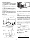
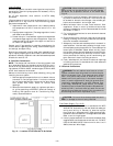
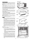
II. UNIT DUCT CONNECTIONS
On vertical units, secure all ducts to roof curb and building
structure. Do not connect ductwork to unit. On horizontal units,
duct flanges should be attached to horizontal openings and
all ductwork should be secured to flanges. Insulate and weath-
erproof all external ductwork, joints, and roof openings with
counter flashing and mastic in accordance with applicable codes.
Ducts passing through an unconditioned space must be in-
sulated and covered with a vapor barrier.
If a plenum return is used on a vertical unit, the return should
be ducted through the roof deck to comply with applicable
fire codes.
A minimum clearance is not required around ductwork.
Cabinet return-air static shall not exceed −0.35 in. wg with
Varislide™ economizer, −0.35 in. wg with PARABLADE econo-
mizer, or −0.45 in. wg without economizer.
NOTE: Connection must be made to roof curb before unit is
set in place.
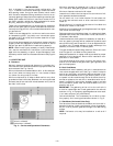
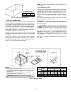
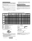
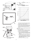
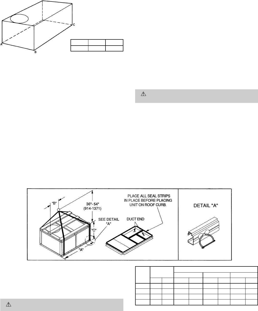
III. RIG AND PLACE UNIT
Inspect unit for transportation damage. File any claim with
transportation agency. Keep unit upright and do not drop.
Spreader bars are not required if top crating is left on unit.
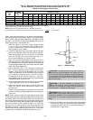
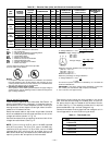
Rollers may be used to move unit across a roof. Level by us-
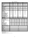
ing unit frame as a reference. See Table 1 and Fig. 6 for ad-
ditional information. Operating weight is shown in Table 1
and Fig. 6.
Lifting holes are provided in base rails as shown in Fig. 6.
Refer to rigging instructions on unit.
IMPORTANT: If unit has forklift protection skids, be sure to
remove forklift protection skids from under unit before set-
ting unit in place.
CAUTION:
All panels must be in place when
rigging.
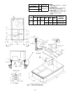
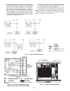
A properly positioned unit will have the following clearances
between unit and roof curb:
1
⁄
4
-in. clearance between roof curb
and base rails on each side and front of unit; 1
5
⁄
32
-in. clear-
ance between roof curb and rear of unit. See Fig. 4, Views
A-A and C-C.
After unit is in position, remove shipping materials and rig-
ging skids.
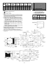
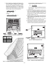
NOTES:
1. Dimension in ( ) are in millimeters.
2. Hook rigging shackles through holes in base rail as shown in detail
‘‘A.’’ Holes in base rails are centered around the unit center of grav-
ity. Use wooden top skid when rigging to prevent rigging straps from
damaging unit.
3. Weights include base unit without economizer. See Table 1 for unit
operating weights with an economizer.
CAUTION: All panels must be in place when rigging.
UNIT
581B
MAX
WEIGHT
DIMENSIONS
‘‘A’’ ‘‘B’’ ‘‘C’’
Lb Kg in. mm in. mm in. mm
036 530 240 73.69 1872 35.50 902 33.31 847
048 540 245 73.69 1872 35.50 902 33.31 847
060 560 254 73.69 1872 35.50 902 33.31 847
072 615 279 73.69 1872 35.50 902 33.31 847
Fig. 6 — Rigging Details
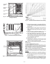
MAXIMUM ALLOWABLE
DIFFERENCE (in.)
A-B B-C A-C
0.5 1.0 1.0
Fig. 5 — Unit Leveling Tolerances
—5—