


BES-962BC • BES-1262BC
258
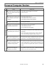
Chapter 12 Troubleshooting
Symptom Measures
Thread trimming motor zero point
error occurs.
• Is lint clogged between the travelling blades?
Remove it.
• Is the thread trimming motor operating?
If so, refer to the block diagram showing the cable connections and
check to see if connection from the thread breakage sensor to the main
PCB is proper. Also adjust the thread breakage sensor PCB. (Refer to
"Replacing thread breakage sensor PCB.)
• If it is not operating, refer to the block diagram showing the cable
connections and check to see if connection from the thread trimming
motor to the main PCB is proper.
• Check to see if connection from connector P3 of the main PCB to
connector P9 of the power supply PCB in the control box is proper.
• Check fuse F6 on the power supply PCB in the control box.
If it is blown, replace it with a new one. If it is blown again, replace
the power supply PCB.
Power frequency error occurs. • Check to see if connection from connector P16 of the main PCB to
connector P10 of the power supply PCB in the control box is proper.
• Refer to the block diagram showing the cable connection and check to
see if connection from connector P26 of the power PCB in the control
box to connector P7 of the power supply PCB in the power supply base
is proper.
• Check fuse F3 on the power supply PCB in the power supply base.
If it is blown, replace it with a new one. If it is blown again, there is
a fault somewhere in the 24v system circuit.
Wiper out error occurs. • Does the wiper on the error head remain projected?
If the wiper is tangled with a thread, remove it. If the wiper does not
return smoothly, adjust it.
• Enter the solenoid test mode and operate the wiper solenoid. Check the
icon on the panel.
If a sensor signal is not given, check to see if connection from the
wiper sensor to the head PCB is proper. Replace the wiper sensor
with a new one. Replace the head PCB with a new one.
• Is the red LED for the BC PCB off?
If not, refer to the block diagram showing the cable connections and
check to see if the connection from the BC PCB to the main PCB is
proper.
• Check to see if connection from the lower shaft motor to the BC PCB of
the bed on BC PCB whose red LED is off is proper.
Replace the harness or the lower shaft module if a short circuit
occurs due to line insertion.
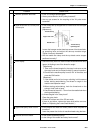
• Measure the resistance values of pin 1 and pin 2, pin 2 and pin 3, pin 3
and pin 4, pin 4 and pin 5, and pin 5 and pin 1 at the connector of the
lower shaft motor with the tester and check to see if they are
approximately 2.6Ω.
Replace the faulty lower shaft module with a new one.
• Replace the BC PCB with a new one.
Lower shaft motor overcurrent error
occurs.