


BES-962BC • BES-1262BC
256
Chapter 12 Troubleshooting
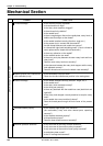
Symptom Measures
The thread breakage error frequently
occurs although thread is not broken.
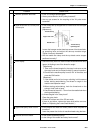
• Enter the CASE test mode and turn the thread breakage sensor pulley
corresponding to each needle bar of the head with which this error
occurs while switching the needle bar from number 1 in ascending
order and check to see that the red LED on the head blinks.
If there is no problem, lower the thread breakage sensitivity value of
the machine controller. (The standard value is 0.)
• Check connection from the thread breakage sensor PCB to the head
PCB if it does not blink.
• Replace the thread breakage sensor PCB with a new one.
The X-axis motor connector connec-
tion error occurs.
• Refer to the block diagram showing the cable connections and check
the connection from the two X motors on the left and right to the main
PCB.
• Enter the encoder signal mode and manually turn the main shaft pulley.
If it is abnormally heavy, the main shaft mechanism is faulty.
• Does the main shaft motor rotate at all when the error occurs?
If it does not rotate at all, check fuse F5 on the power supply PCB in
the control box. Refer to the block diagram showing the cable
connections and check to see if connection from the main shaft motor
to the main PCB is proper. Also check connection of connectors P6
and P4 of the main PCB and connectors P19 and P12 on the power
PCB in the box, and connection from connector P11 of the power supply
PCB to the 14v terminal of the power transformer.
• Manually turn the main shaft pulley in the encoder signal test mode and
check to see if the stop position signal and encoder signal are proper.
If either of the signals does not change, refer to the block diagram
showing the cable connections and check to see if connection from the
encoder and stop position sensor to the main PCB is proper.
The main shaft motor lock error oc-
curs.
• Check the CPU ROM version for the upper shaft.
If it is version A, replace it with the latest ROM of version B or later.
(PROM#4 on the main PCB)
ERROR A7 occurs.
• In the encoder signal test mode, manually turn the main shaft pulley
and check to see that the stop position signal is correct.
If the signal does not change, refer to the cable connection block
diagram and check to see if connection from the stop position sensor
to the main PCB is proper.
ERROR A8 frequently occurs.
X-axis or Y-axis home position de-
tection error occurs.
• Was the XY carriage moving?
If so, refer to the block diagram showing the cable connections and
check to see if connection from the X and Y area sensor to the main
PCB is proper.
• Was the XY motor rotating?
If so, check the XY carriage mechanism.
• If the XY motor is not rotating, refer to the cable connection block
diagram and check to see if connection from the XY motor to the main
PCB is proper.