8 Circuit Connection Details
8.1 2-16 Zone Motherboard Termination Details
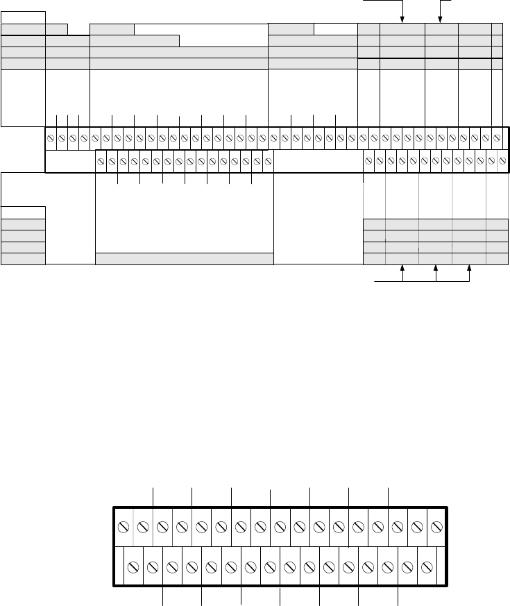
Figure 8 - C1627 Field Termination
Zone O/Ps
2
4
8
16/32
1234
Zone Circuits
56781234
+
-
+
-
+
-
+
-
+
-
+
-
+
-
+
-
2
4
8
16/32
Zone Circuits
13 14 15 169101112
+
-
+
-
+
-
+
-
+
-
+
-
+
-
+
-
Grey fill indicates I/O available on selected panel
Alarm Circuits
1234
+
-
+
-
+
-
+
-
Aux
DC
24V
0V
SIL
Inputs
Outputs Repeater
EVAC
RST
DIS
EVAC
A
B
SCN
Reset N/C
Inputs:
SIL = Silence alarms
EVAC = Evacuate
RST = Reset
Outputs:
DIS = Disablement active
EVAC = Evacuation active
BUZ Active = Buzzer active
Class change
Buz Active
Lower terminal tier
Upper terminal tier
Lower terminal tier
Upper terminal tier
Fault
Routing
24 V
0V
O/+
P
C/-
N/O
P
Aux
DC
O/- = Normally Open or -ve
O/+ = Normally Open or +ve
P = Pole
C/+ = Normally Closed or +ve
C/- = Normally Closed or -ve
Fire
Routing
C/+
P
O/-
Fire
Protection
C/+
P
O/-
Reset
Grey fill indicates I/O available on selected panel
8.2 16 Zone Expansion Board Termination Details
Figure 9 - C1632 16-Zone Expansion Board Field Termination
Zone Circuits
21 22 23 2417 18 19 20
+
-
+
-
+
-
+
-
+
-
+
-
+
-
+
-
Zone Circuits
29 30 31 3225 26 27 28
+
-
+
-
+
-
+
-
+
-
+
-
+
-
+
-
Lower terminal tier
Upper terminal tier
Page 9 of 40


