


8. Disconnect the flying leads from the transformer to the mains terminal block and earth
bar.
9. Remove the chassis from the enclosure and place carefully to one side.
NOTE: The door and chassis both contain PCBs with sensitive and fragile electronic
components on them. You must place these items in a location where they will
not be damaged. Choose an area that is clean, dry and dust-free. You can place
the items inside the original packing carton but you must ensure that sufficient
soft packing is used to keep the door and chassis separated.
10. Identify the three indented holes in the backbox that are used to mount the enclosure.
11. Place the enclosure in the desired location and mark the position of the top indented hole.
Remove the enclosure and fit a suitable fixing to the wall. Hang the enclosure from the
top fixing point and ensure that it is level. Mark the locations of the other two mounting
holes.
12. Remove the enclosure from the wall and fit suitable fixings to the two remaining mounting
points. Fix the enclosure to the wall using all three mounting points.
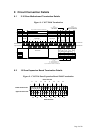
13. Carefully remove the required knock-outs in the panel enclosure and gland all field wiring
in place ensuring that the cable conductors are of sufficient length inside the enclosure.
Ensure that all conductors are clearly labelled. DO NOT remove knock-outs from any
unused cable entries. Any unused cable entries which are open must be sealed
with a suitable plug (available separately).
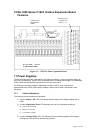
14. Connect the earth drain wires of the field cabling to the brass earth bar positioned at the
top of the backbox. Up to two drain wires may be connected to each terminal.
15. Ensure that continuity of any cable shield is maintained through to the last device on the
circuit. The shield must only be connected to enclosure earth in the panel by using the
earth bars provided. [Different requirements apply for the screen of data cable used for
connecting repeaters – see 12.2.2 below].
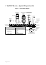
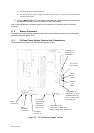
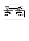
16. Connect the incoming protective earth conductor to the Earth terminal in the mains
terminal block. This is the primary earth point and is labelled
[also labelled E]. See
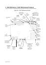
Internal Panel Views
17. Clear any dust and debris from inside the enclosure.
18. Connect the mains-in LIVE cable to the mains terminal block [L terminal] as indicated in
Internal Panel Views.
20. Connect the mains-in Neutral cable to the mains terminal block [N terminal] as indicated
in Internal Panel Views.
21. Secure the mains-in cable to the cable clamp adjacent the mains terminal using the cable
tie supplied. NOTE: The clamp should be over the outer cable insulation.
22. Reinstallation of the chassis is the reverse of removal. Reconnect all wires and ensure
none are trapped between the chassis and back-box. Do not connect the field wiring at
this stage.
23. Refit the door. The refitting procedure is the reverse of removal. Ensure that the earth
strap and ribbon cable are reconnected correctly.
24. Place the left-hand battery into the bottom of the enclosure. The terminals should be
positioned towards the centre of the enclosure and the battery should be adjacent to the
left side of the back-box, fixed by the raised indents in the back-box, one above the
battery and one to the right.
Page 16 of 40